Ball Valve with Offset Straight Through Flow

a ball valve and straight through flow technology, applied in the field of valve technology, can solve the problems of increasing the power requirement of actuating the valve, the relative size of the valve member, and the increase of the cost of procurement and operation of the ball valve, so as to reduce the overall size

Inactive Publication Date: 2013-01-03
SCHNEIDER ELECTRIC BUILDINGS LLC
View PDF4 Cites 12 Cited by
  • Summary
  • Abstract
  • Description
  • Claims
  • Application Information

AI Technical Summary

Benefits of technology

[0018]In another aspect, embodiments of the present invention provide a ball valve having a reduced overall size as a result of a compact valve member associated therewith. An embodiment of a ball valve according to this aspect has a fully opened position to allow fluid flow through the ball valve, and a fully closed position to prevent fluid flow through the ball valve. The ball valve includes a housing having an inlet and an outlet and a flow path extending therebetween. A valve member is positioned within an internal cavity of the housing between the inlet and the outlet and within the flow path to selectively transition the ball valve between the fully opened and fully closed positions. The valve member has a straight passageway. The passageway has a non-circular cross sectional profile and defines a valve member flow axis passing through a center of the passageway.

Problems solved by technology

With the above description of a typical ball valve in hand, several problems arise from the same.
Accordingly, the size of the passageway in addition to the size of the increased wall thickness of the valve member results in a relatively large valve member.
The aforementioned size constraints of a typical ball valve can also lead to higher power requirements to actuate the valve.
As a result, the relatively large size of a typical spherical ball valve member drives up the size and power requirements of such actuators, and thus increases the cost of procurement and operation of the ball valve.
Such a requirement also disadvantageously increases the power requirements to actuate the valve.

Method used


Image

  • Ball Valve with Offset Straight Through Flow
  • Ball Valve with Offset Straight Through Flow
  • Ball Valve with Offset Straight Through Flow

Examples


Embodiment Construction

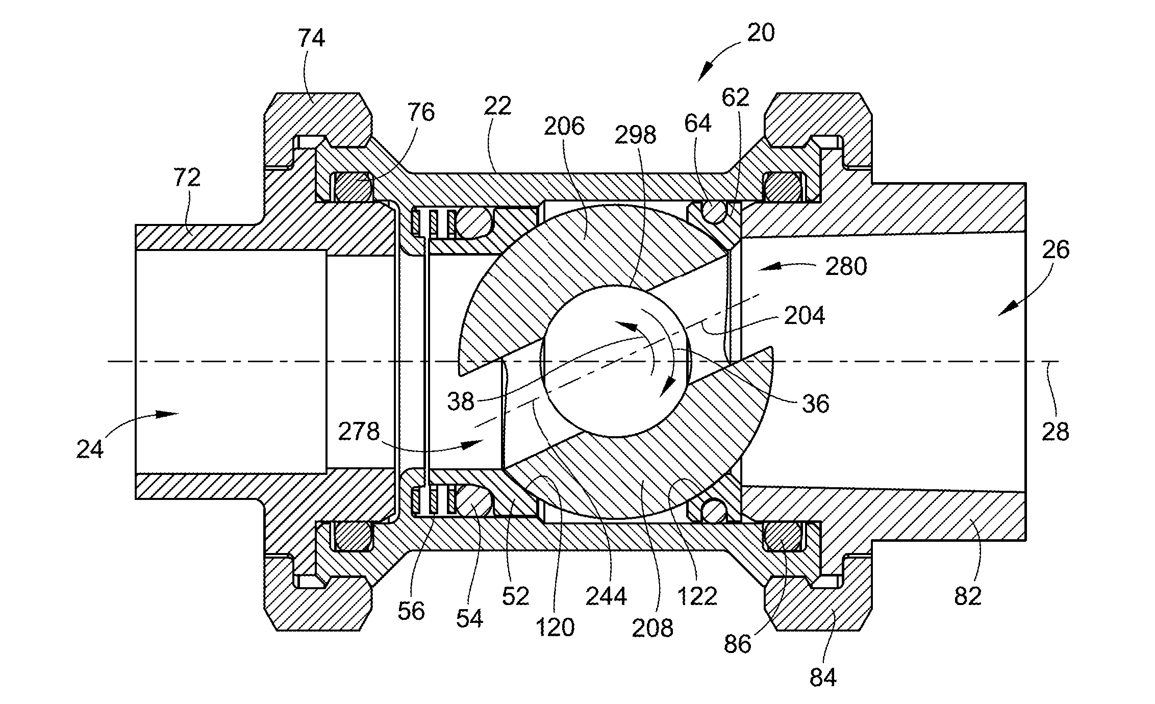
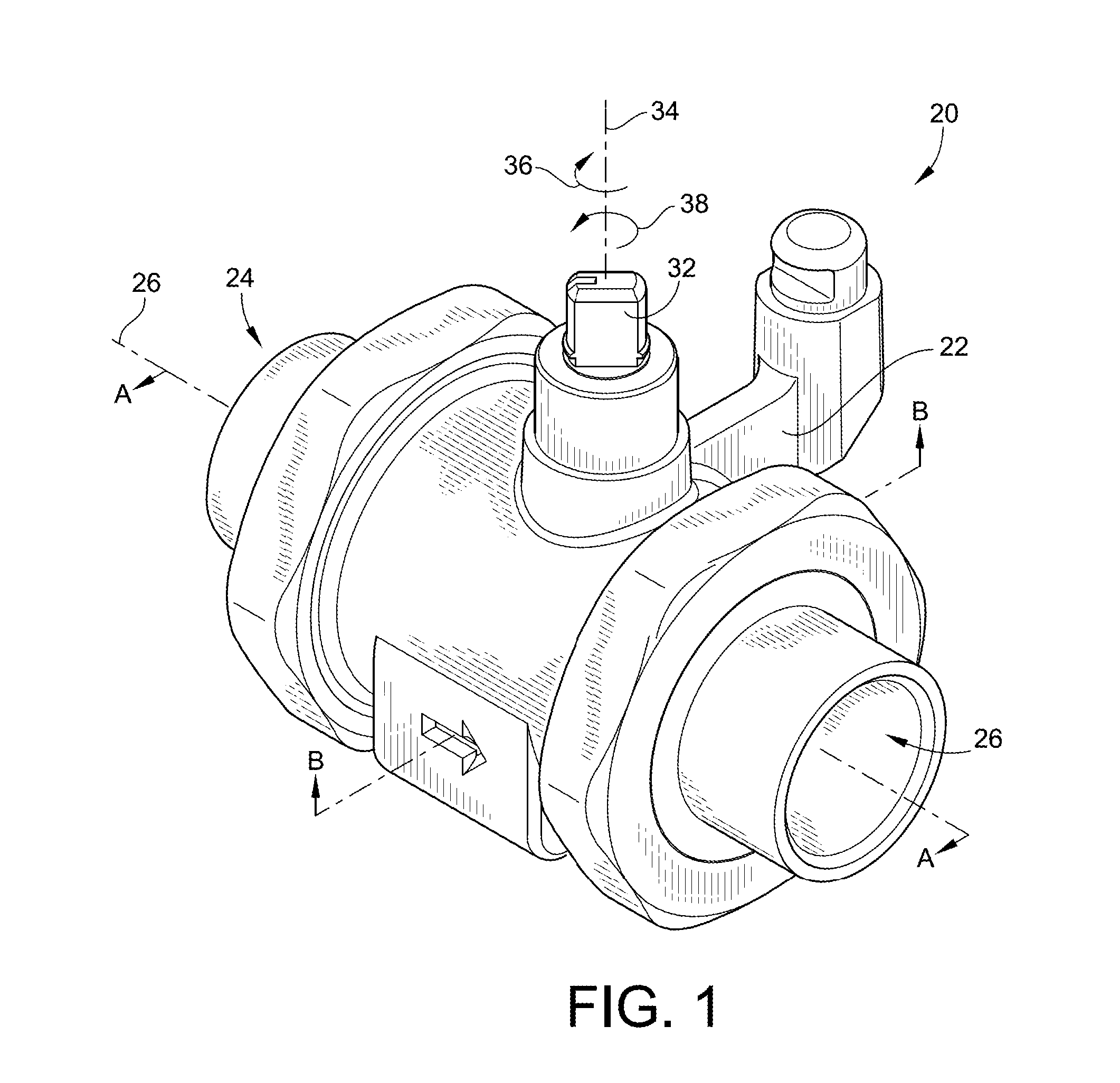
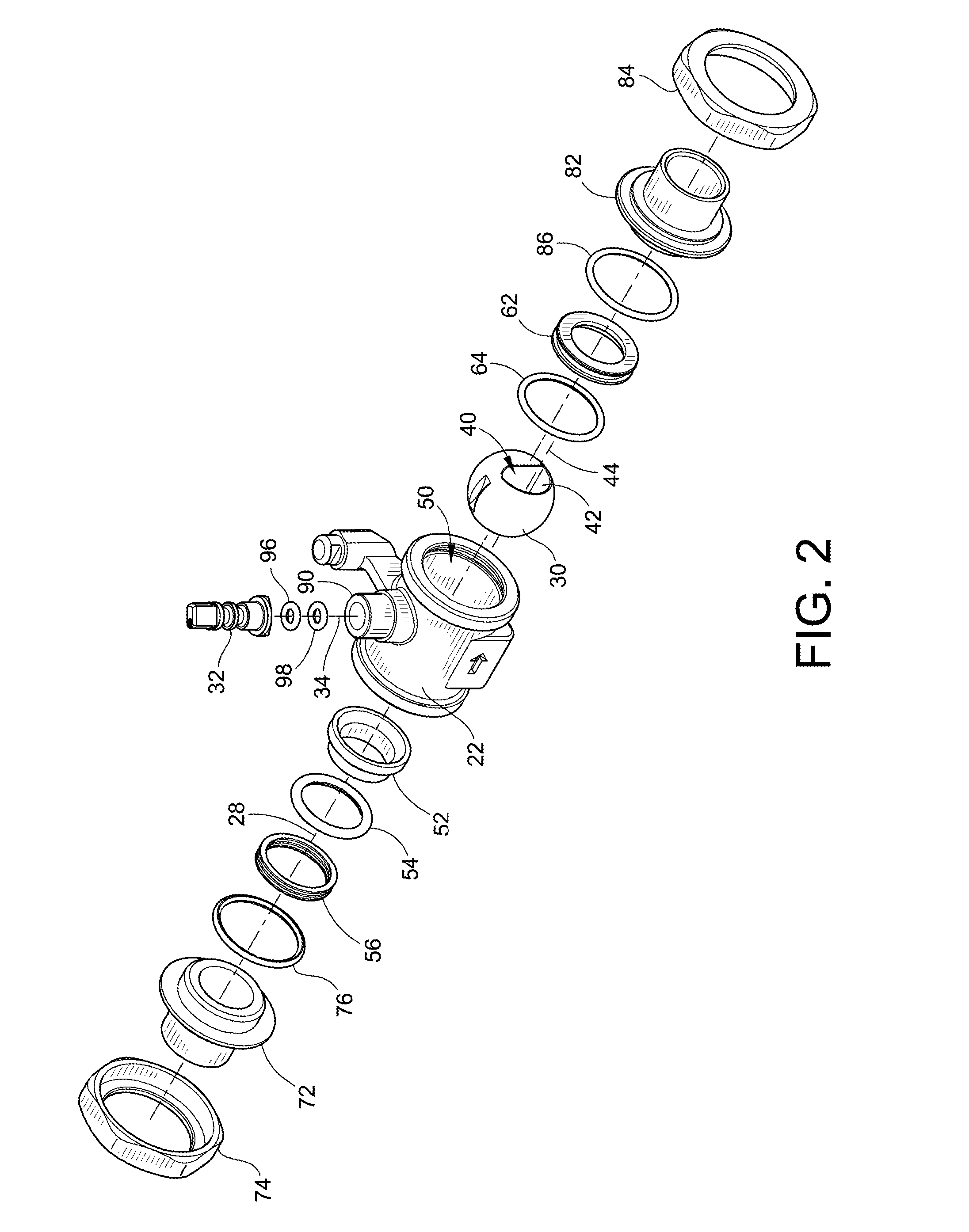
[0041]Turning now to the drawings, there is illustrated in FIG. 1 an exemplary embodiment of a ball valve 20 according to the teachings of the present invention. The ball valve 20 includes a housing 22. The housing 22 has an inlet 24 and an outlet 26 axially aligned with the inlet 24 along a flow path represented by a flow path axis 28. The flow path axis 28 extends through the ball valve 20 and generally represents the course of fluid flow from the inlet 24 to and through the outlet 26. As used herein, the term “fluid” contemplates liquids, gases, liquid-gas mixtures, and slurries. Indeed, it will be recognized by those skilled in the art that the ball valve 20 is not limited in its application to any particular type of fluid.

[0042]A valve stem 32 of the ball valve 20 extends from an exterior of the housing 22 into an internal cavity 50 (see FIG. 2) of the housing 22. The valve steam 32 is rotatable about a valve stem axis 34 in first and second rotational directions 36, 38 to sele...


PUM


Abstract

A ball valve with offset straight through flow is provided. The ball valve has a housing having an inlet and an outlet and an internal cavity. A non-spherical ball valve member is positioned within the internal cavity. The valve member is mechanically coupled to a valve stem extending from the internal cavity to an exterior of the housing such that rotation of the valve stem results in a like rotation of the valve member. The ball valve has a fully closed position wherein fluid flow therethrough is prevented. The ball valve member also has a fully opened position where fluid flow therethrough is allowed. The ball valve can transition from the fully closed position to the frilly opened position and vice versa with a rotation of the valve member of less than or equal to about forty-five degrees.

Description

FIELD OF THE INVENTION[0001]This invention generally relates to valve technology, and more particularly to ball valves and their associated valve members.BACKGROUND OF THE INVENTION[0002]Ball valves are generally known in the art and used in a variety of applications ranging from liquid to gas flow control. A typical ball valve includes a housing, also often referred to as a valve body, that has an internal cavity and an inlet and an outlet in fluid communication with the internal cavity. A flow path extends from the inlet, through the cavity, and through the outlet.[0003]A spherical valve member is positioned in the flow path within the internal cavity of the housing. The valve member has a passageway extending entirely through the center of the valve member. A variety of seals can be employed within the internal cavity and adjacent the valve member to restrict flow through the passageway of the valve member, and prevent fluid from freely flowing around the valve member that would ...

Claims


Application Information

Patent Timeline
Patent Type & Authority Applications(United States)
IPC IPC(8): F16K5/06
CPCF16K5/0605
Inventor THOMAS, KURT R.
Owner SCHNEIDER ELECTRIC BUILDINGS LLC
Why Eureka
Try Eureka