Method and apparatus for making foam-in-place cushions with selective distribution of foam

a foam-in-place cushion and selective distribution technology, which is applied in the direction of turning machine accessories, drawing profiling tools, packaging, etc., can solve the problems of uneven distribution of the foam-forming composition as it is discharged from the apparatus, affecting the uniformity of foam density, so as to reduce the incidence of rupturing the transverse seal by forceful dispensing of the foam-forming composition. , the effect of eliminating the incidence of rup

Active Publication Date: 2007-11-01
SEALED AIR U S
View PDF34 Cites 19 Cited by
  • Summary
  • Abstract
  • Description
  • Claims
  • Application Information

AI Technical Summary

Benefits of technology

[0026] At the beginning of a cushion-making cycle, a transverse seal of the film portions can be disposed downstream of the dispersion member and drive roller, and the dispersion member can be placed in nipping engagement with the drive roller so as to press the film portions against the drive roller. Accordingly, when the foam-forming composition is dispensed between the film portions, the transverse seal is initially isolated from the foam-forming composition by the nipping engagement between the dispersion member and drive roller. The incidence of rupturing of the transverse seal by forceful dispensing of the foam-forming composition is thereby substantially reduced or eliminated.
[0027] The invention enables selective, controlled placement of foam in a cushion by controlling variables such as movement of the foam dispenser, speed of dispenser movement, advancement of the film portions, speed of film advancement, “on” and “off” operation of the dispenser, and operation of the dispersion member for controlling foam thickness.

Problems solved by technology

In this regard, one difficulty associated with conventionally produced foam-in-place cushions is that the cushion as it is discharged from the apparatus does not have the foam-forming composition evenly distributed in the cushion.
The problem with this technique is that by the time the operator is able to get the cushion onto the flat surface, the foam-forming composition has already undergone a substantial degree of expansion.
Moreover, the uniformity of the foam density may be compromised, such that substantial non-uniformities of density may be created in the cushion.
Consequently, the cushion may not have the protective properties it was designed to have.

Method used


Image

  • Method and apparatus for making foam-in-place cushions with selective distribution of foam
  • Method and apparatus for making foam-in-place cushions with selective distribution of foam
  • Method and apparatus for making foam-in-place cushions with selective distribution of foam

Examples


Embodiment Construction

[0049] The present inventions now will be described more fully hereinafter with reference to the accompanying drawings in which some but not all embodiments of the inventions are shown. Indeed, these inventions may be embodied in many different forms and should not be construed as limited to the embodiments set forth herein; rather, these embodiments are provided so that this disclosure will satisfy applicable legal requirements. Like numbers refer to like elements throughout.

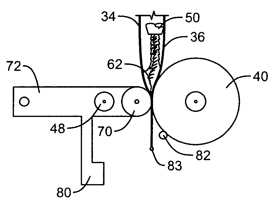
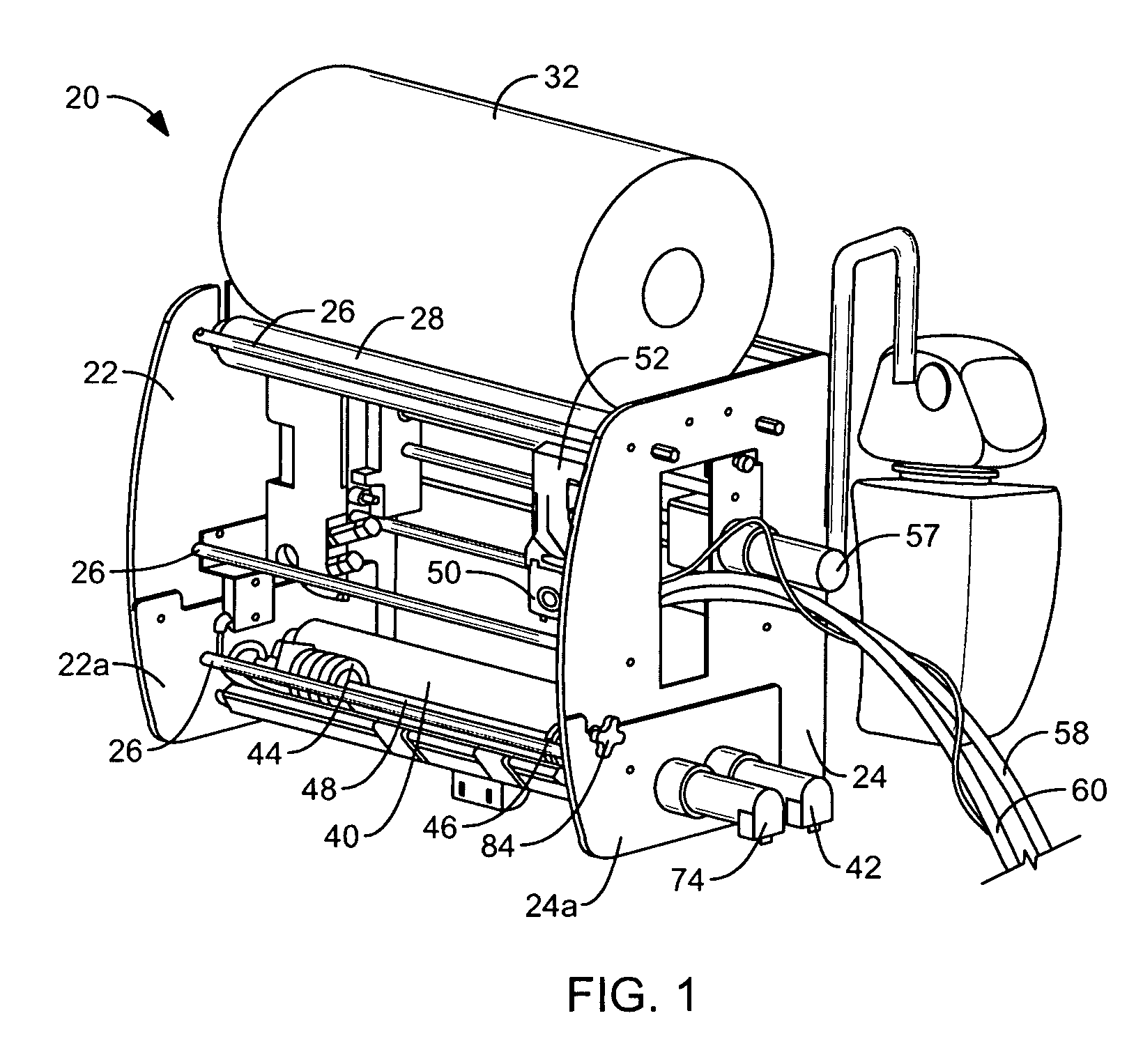
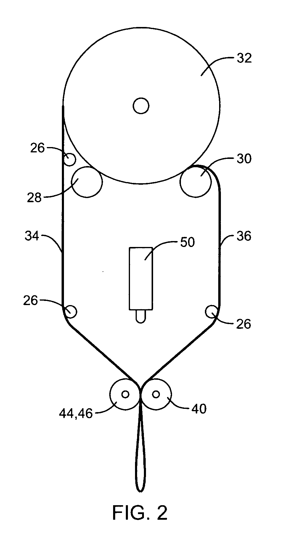
[0050]FIGS. 1 through 3 depict an apparatus 20 for making foam-in-bag cushions in accordance with one embodiment of the invention. The apparatus includes a pair of spaced-apart, parallel frame members 22, 24 each of which is generally in the form of a plate, and a plurality of support rods 26 or the like that are connected between the frame members 22, 24 to form a generally rigid frame. At the top end of the frame, a pair of freely rotatable idler rollers 28, 30 are rotatably supported between the frame membe...


PUM

PropertyMeasurementUnit
thicknessaaaaaaaaaa
lengthaaaaaaaaaa
thicknessaaaaaaaaaa

Abstract

A method and apparatus for making a foam-in-place cushion in which a foam-forming composition is dispensed between two plastic film portions in a predetermined fashion to selectively control the distribution of the foam in the cushion. A foam dispenser can be moved in a transverse direction as foam is dispensed. A dispersion device can be employed to apply pressure on predetermined areas of the film portions towards each other so as to cause the composition to be redistributed in position in a predetermined manner while the composition is in a less than fully expanded state. The plastic film can then be sealed closed to form an expanding foam cushion that can be placed into a shipping carton where the cushion expands to fill void space, or into a mold where the cushion expands and is molded into a desired shape.

Description

BACKGROUND OF THE INVENTION [0001] The present invention relates to a method and apparatus for making foam-in-place cushions having a foam-forming composition contained within a flexible bag formed from polymer film supplied as continuous web material, the polymer film being sealed along longitudinal and transverse seals to contain the foam-forming composition, and being severed to detach a foam-in-place cushion from the remaining web material. [0002] Foam-in-place packaging is a highly useful technique for on-demand protection of packaged objects. In its most basic form, foam-in-place packaging comprises injecting a foam-forming composition from a dispenser into a container that holds an object to be cushioned. Typically, the object is wrapped in plastic to keep it from direct contact with the rising (expanding) foam. As the foam rises, it expands into the void space between the object and its container (e.g., a corrugated board box), thus forming a custom cushion for the object. [...

Claims


Application Information

Patent Timeline
Patent Type & Authority Applications(United States)
IPC IPC(8): B29C44/12
CPCB29C44/184B29C44/60B29C44/467B29C44/588B65D65/00B65D81/00
Inventor SPERRY, CHARLESSCOTT, SUZANNEMCNAMARA, DENNISPIUCCI, VINCENTSCHAMEL, MICHAEL
Owner SEALED AIR U S
Why Eureka
Try Eureka