Frame system with releasable couplers

a frame system and coupler technology, applied in the direction of rod connections, fastening means, constructions, etc., can solve the problems of inability to carry loads, inability to use thin-wall materials, and inability to meet the requirements of construction, etc., to achieve quick and easy jointing of the frame components to each other.

Inactive Publication Date: 2007-11-22
HOWE IAN +1
View PDF15 Cites 31 Cited by
  • Summary
  • Abstract
  • Description
  • Claims
  • Application Information

AI Technical Summary

Benefits of technology

[0006] It is the primary objective to provide a structural frame system that has frame members and joining couplers which are quickly and releasably joinable to each other.

Problems solved by technology

This method is limited to the use of thin-wall materials, since the tabs, holes or slots are formed by processes such as stamping.
Structural components compatible with these processes are typically thin-walled angle-sections, which are, structurally, less efficient than sections such as rectangular hollow sections.
The assembled frame components are relatively limited in load-carrying capacity, and lack relative strength and stability.
In addition, the completed frame is unsightly due to the exposed joining elements as well as vacant holes.
This second prior-art method is limited in that the posts and rails may be joinable only by utilizing connectors which can be slid inside the ends of both sections.
Consequently, a rail may not easily be joined into or removed from an already constructed frame.
This method also lacks versatility and is cumbersome.
This method is cumbersome and time-consuming to assemble, and the position of the rail along the post may need to be determined at each and every connection.
This method also has unsightly exposed screws and requires special tools to assemble.
In addition, owing to the use of a single bolt, the rail often lacks resistance to high torsion, and, since the end of the rail forcibly abuts against the face of the post surface to create a friction grip, marring may occur.
Also, a rail may not be easily added or removed from a completed frame, since rails have depth in the longitudinal direction of posts.
This method may be equally cumbersome and time-consuming to assemble.
This method also employs exposed unsightly grub-screws, and requires tools to assemble.
Also, since the end of the rail forcibly abuts against the face of the post to create a friction grip surface, marring of the post surface is possible, and, also, a rail is not easily added or removed from a completed frame since rails have depth in the longitudinal direction of posts.

Method used


Image

  • Frame system with releasable couplers
  • Frame system with releasable couplers
  • Frame system with releasable couplers

Examples


first embodiment

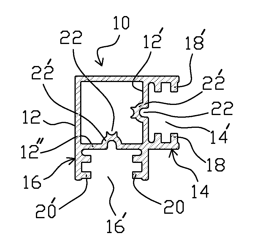
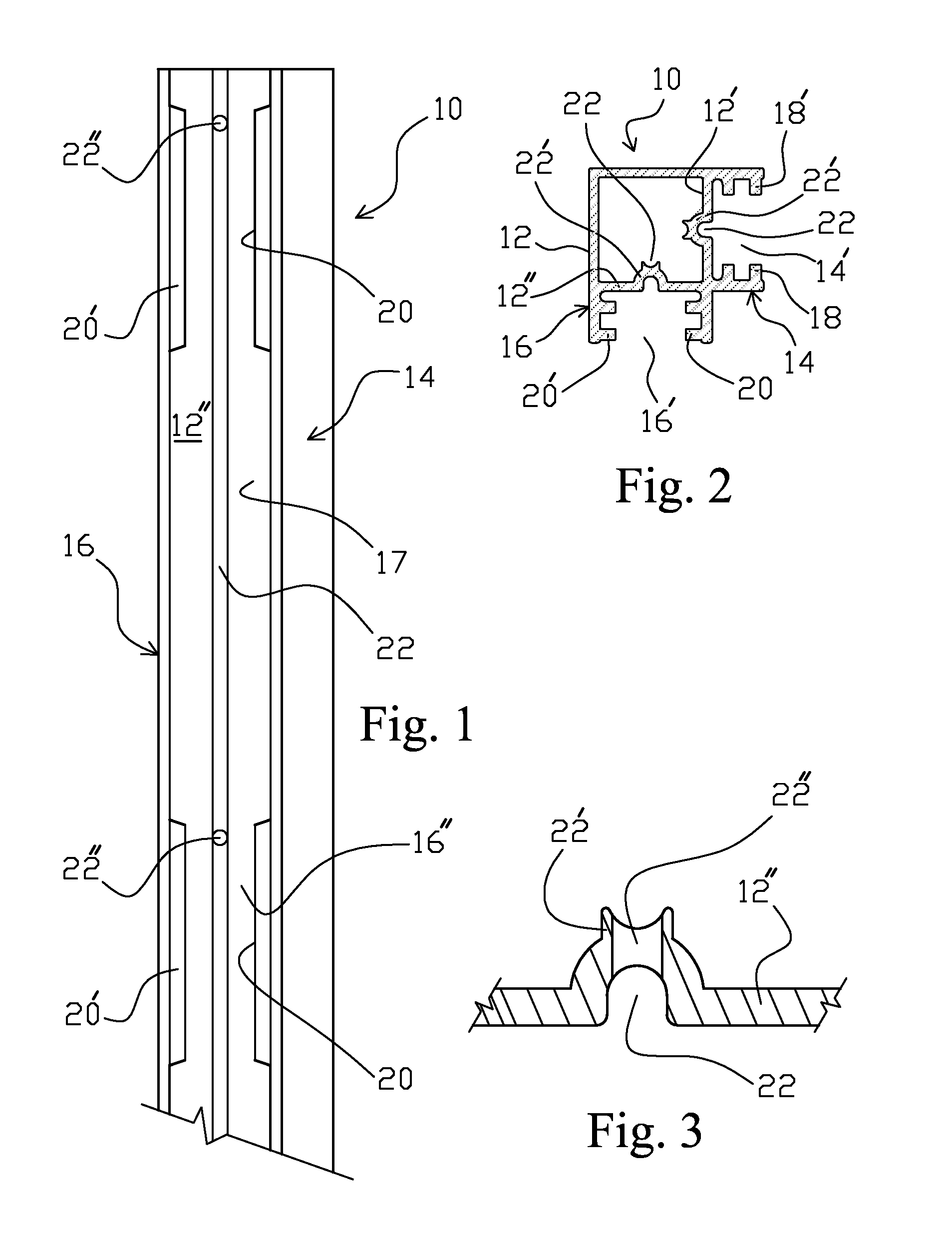
[0068] The sleeve 126 is loosely mounted within one of the elongated web sections 114, 116 by means of cams or wedge-elements 122 located in the interior portion of the web section in close juxtaposition to the associated surface-face or wall of the elongated main section 112 from which the respective web section 114 or 116 projects, as seen in FIGS. 25A-27. The lateral distance between the two cams 122 is such as to loosely retain the sleeve member 126 and cause compression of the sleeve member 126 as it is slid in the web section 114 or 116 and reaches the cam members 122. It is noted that sleeve member 126 is inserted into a web section 114 or 116 at one of the free ends of the web section, and then slid toward the pair of cam members. The free edge-surfaces 128 may be squeezed toward each other by the camming members 122. In any case, the free edge-surfaces 128 are to provide the equivalent of the narrower-gap section 16″ of FIG. 1, whereby these free ends are clearly visible, a...

second embodiment

[0072] In a modification the coupler component 118 of the second embodiment shown in FIG. 31A, a double connector 118′ is provided by which the ends of two rail components may be coupled together, in the manner shown in FIG. 39. The double connector 118′ consists of two regular coupler components 118 arranged back-to-back such that the narrower sections 164 face toward each other and are separated by a central spacer element 170, defining an upper and a lower cutout or recess 170′, 170″ in each of which is flush-mounted a bent end 172 of one of the wider sections 168. This double connector 118′ is used for connecting together two post components parallel to each other, as shown on FIG. 39, with the parallel-arranged, or back-to-back, post components being oriented 180m degrees opposite to each when mounted in such a back-to-back connection. For those rail components that are also provided with web-sections similar to web-sections 14 and 16 of the post component 10, the double connec...


PUM


Abstract

Structure and method for assembling a structural frame for use in erecting temporary or permanent structures, which structural frame has a first component having at least one auxiliary elongated web section with an elongated entrance channel opening for allowing insertion into the hollow interior of a coupler component to which is attached a second component. The channel opening defines a wider gap portion through which a coupler component is inserted, and a narrower gap portion that secures the coupler therein attaching the coupler component to an end of the second component. The first and second components are firmly, yet removable, secured together by first inserting the first wider section of the coupler through the wider gap section of the entrance channel opening of the first component, and then sliding the coupler along the hollow interior of the first component until the wider section is located at and within the narrower gap section of the entrance channel opening of the first component.

Description

BACKGROUND OF THE INVENTION [0001] The present invention relates to structural frame systems, especially those consisting of extruded-aluminum rails or rail-elements and post or post-elements connected together to form a structure, such as a booth, shelving, display, and the like. [0002] Hitherto-known structural frame systems have consisted of particular types of frame members, such as posts and rails, which are joinable together by various means including clips, screws, or joiners to create frames for supporting other members, such as panels. A first such prior-art method has been used for supporting shelf panels, and comprises posts and rails where the posts may contain a series of relatively large holes or slots along their face by which rails containing protruding tabs at their ends are attached. In this method, a shelf-frame is constructed by joining the rails to the posts via the tabs being downwardly receivable within the holes or slots. This method is limited to the use of ...

Claims


Application Information

Patent Timeline
Patent Type & Authority Applications(United States)
IPC IPC(8): E04B1/38
CPCE04B1/58E04B2001/5881E04C2003/0439F16B7/0446E04C2003/0465E04C2003/0469E04C2003/0447
Inventor HOWE, IANPERRY, R. WILLIAM
Owner HOWE IAN
Why Eureka
Try Eureka