Solar panel roof mounting system

a solar panel and mounting system technology, applied in the direction of solar heat collector mounting/support, photovoltaics, solar heat collectors for particular environments, etc., can solve the problem of limited mechanical attachment opportunities on the roo

Inactive Publication Date: 2007-11-22
SOLAR CENTURY HLDG
View PDF32 Cites 109 Cited by
  • Summary
  • Abstract
  • Description
  • Claims
  • Application Information

AI Technical Summary

Benefits of technology

[0006]According to an aspect of the present invention, there is provided an apparatus for securing solar energy collection (SEC) devices to a roof, comprising a plurality of rails, each said rail attachable to a roof at mutually displaced positions and defining a rail slot. Attachment devices ar

Problems solved by technology

Consequently, the roof should not be damaged and opportuni

Method used


Image

  • Solar panel roof mounting system
  • Solar panel roof mounting system
  • Solar panel roof mounting system

Examples


Embodiment Construction

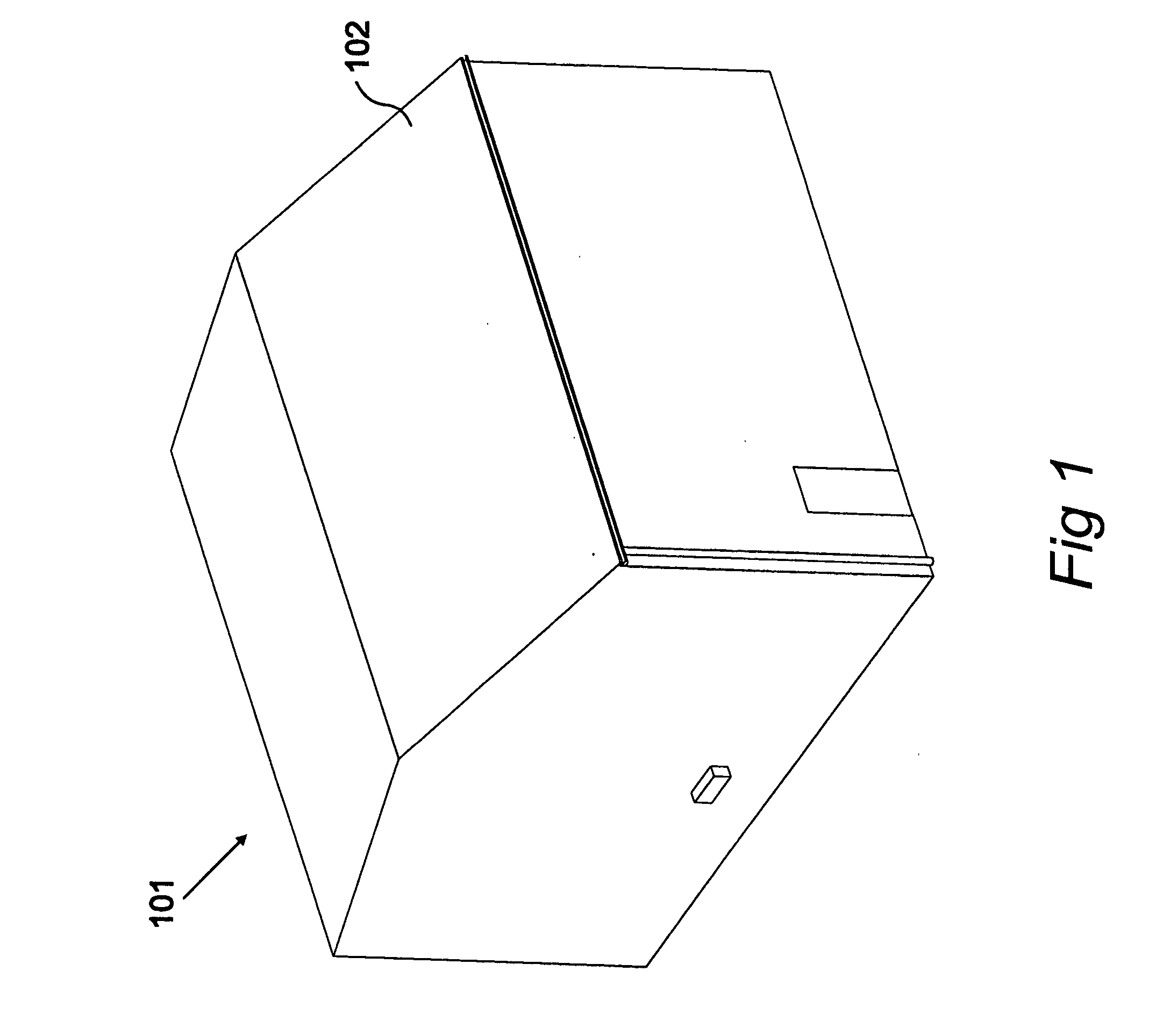
[0022]FIG. 1 shows a commercial building 101, such as a warehouse or factory unit etc. In this example, the building 101 has a modestly sloping roof 102 and it is appreciated that some commercial buildings may have a flat roof.

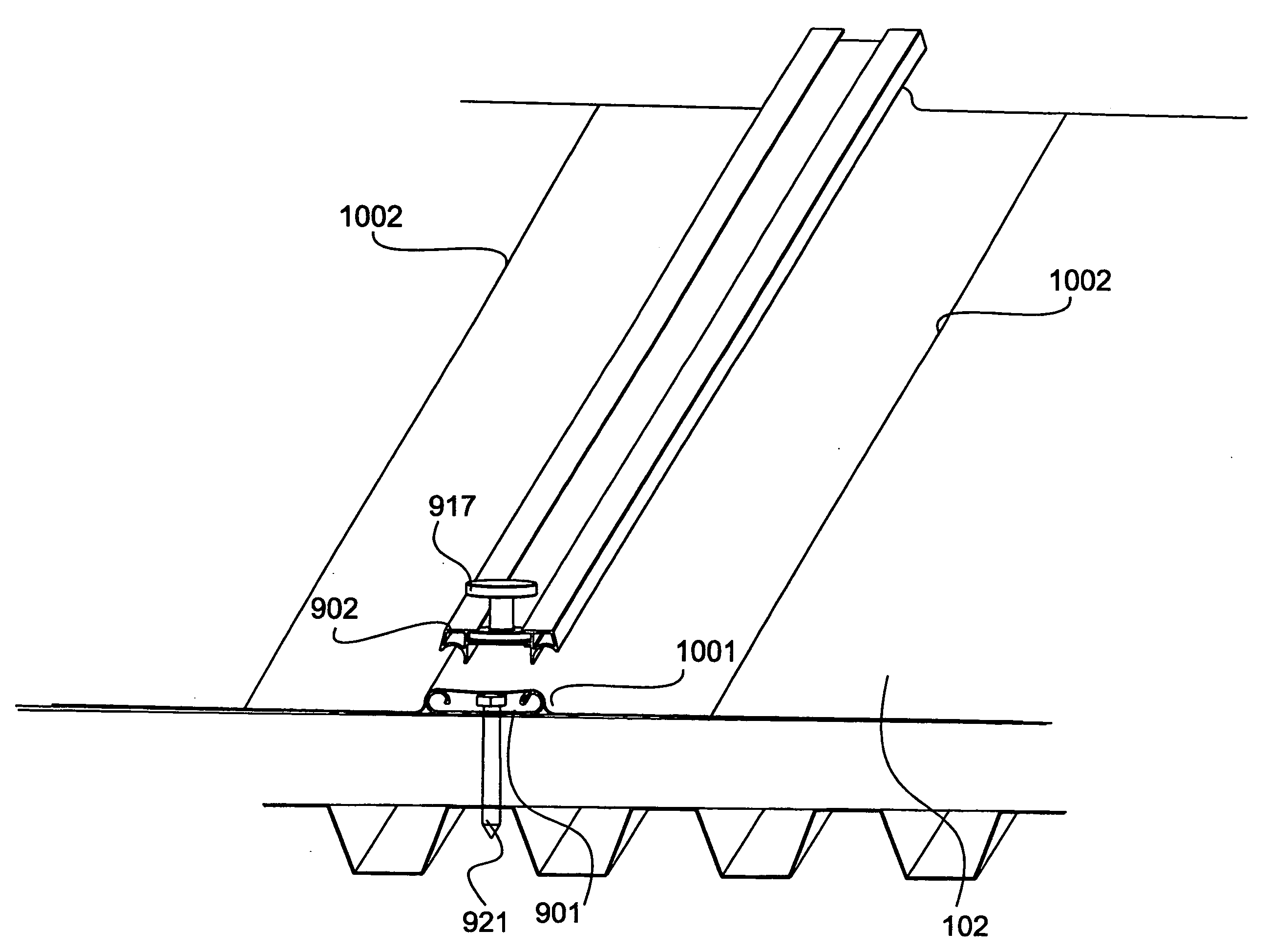
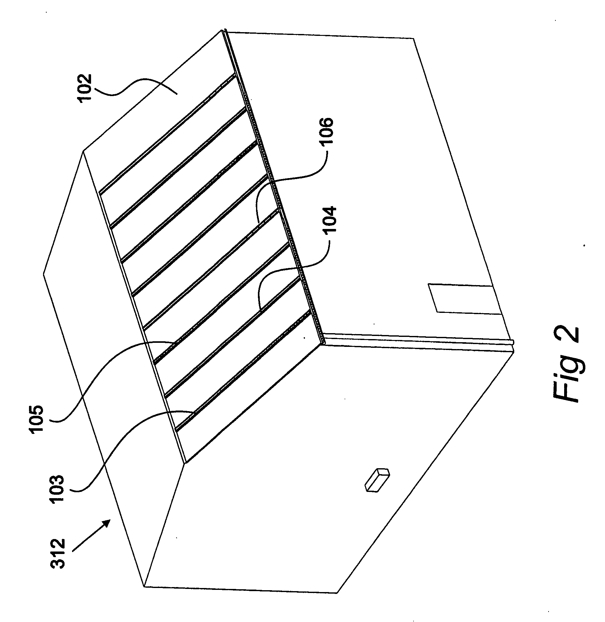
[0023]FIG. 2 shows the building of FIG. 1 onto which rails 103, 104, 105, 106 embodying a preferred aspect of the present invention have been attached. The rails are located at mutually displaced positions and each defines a rail slot, as illustrated subsequently. The rails are provided so as to facilitate the installation of solar energy collection devices on to the roof 102 in which a number of rails 103 to 106 etc are fixed to the roof 102 at mutually displaced positions, with each of the rails including a rail slot. A solar energy collection device is then placed over at least one of the rails and the collection device is attached to said first rail using an attachment device 917 that includes an engagement portion that engages with the rail slot and a pro...


PUM


Abstract

Apparatus is provided for securing solar energy collection devices to a roof. A plurality of rails (103, 104) are provided. Each rail is attachable to a roof (102) at mutually displaced positions and defines a rail slot (702, 915). Attachment devices (917) are provided, each configured to engage with a rail slot (702, 915) such that in a first condition the devices are free to move along the slot and in the second condition the devices are secured within the slot. The attachment devices (917) include an engaging portion (919) that protrudes from the slot to engage with a solar energy collection device.

Description

CROSS REFERENCE TO RELATED APPLICATIONS [0001]This application claims priority from United Kingdom Patent Application No. 06 10 031.7, filed 19 May 2006, the entire disclosure of which is incorporated herein by reference in its entirety.TECHNICAL FIELD [0002]The present invention relates to securing solar energy collection devices to a roof.BACKGROUND OF THE INVENTION [0003]Mounting systems for supporting solar energy collection devices are known, many of which are configured to place the collection devices at a particular orientation, while at the same time providing a firm anchoring.[0004]Many known systems have been attached to buildings and on the whole the collection panels are effectively treated as part of the building, being in common ownership such that an occupant or owner may be responsible both for the solar energy collection systems and the fabric of the building itself.[0005]Increasingly, in the future, it is likely that alternative relationships may be developed in wh...

Claims


Application Information

Patent Timeline
IPC IPC(8): E04B1/00F24S90/00
CPCE04D3/352H02S20/23F24J2/045F24J2/5205F24J2/5235F24J2/5249F24J2/5256F24J2002/4676F24J2002/5222F24J2002/5226F24J2002/5292Y02B10/12Y02B10/20Y02E10/44Y02E10/47E04D5/12F24S20/67F24S25/15F24S25/33F24S25/615F24S25/634F24S2025/02F24S2025/601F24S2025/805F24S2025/807Y02B10/10Y02E10/50E04D13/00F24S25/00H02S20/00
Inventor BATEMAN, LACHLAN SAMUELDAVIES, DANIEL GOWERBRAZIER, SHAY DONALDBERRY, MARTYN JOHN CHARLES
Owner SOLAR CENTURY HLDG
Why Eureka
Try Eureka