Deployable watchtower

a watch tower and deployable technology, applied in the field of watch towers, can solve the problems of watchmen in designated areas being put into dangerous situations, and achieve the effect of reducing the risk of casualties

Inactive Publication Date: 2007-12-13
KLEIN
View PDF13 Cites 5 Cited by
  • Summary
  • Abstract
  • Description
  • Claims
  • Application Information

AI Technical Summary

Problems solved by technology

Watching over specified locations is a matter of securing a specific zone or passage, and may be associated with dangerous or even deadly activities.
Watchmen in their duty of surveillance or inspection over designated areas may be put into dangerous situations during their duty hours.

Method used


Image

  • Deployable watchtower
  • Deployable watchtower
  • Deployable watchtower

Examples


Embodiment Construction

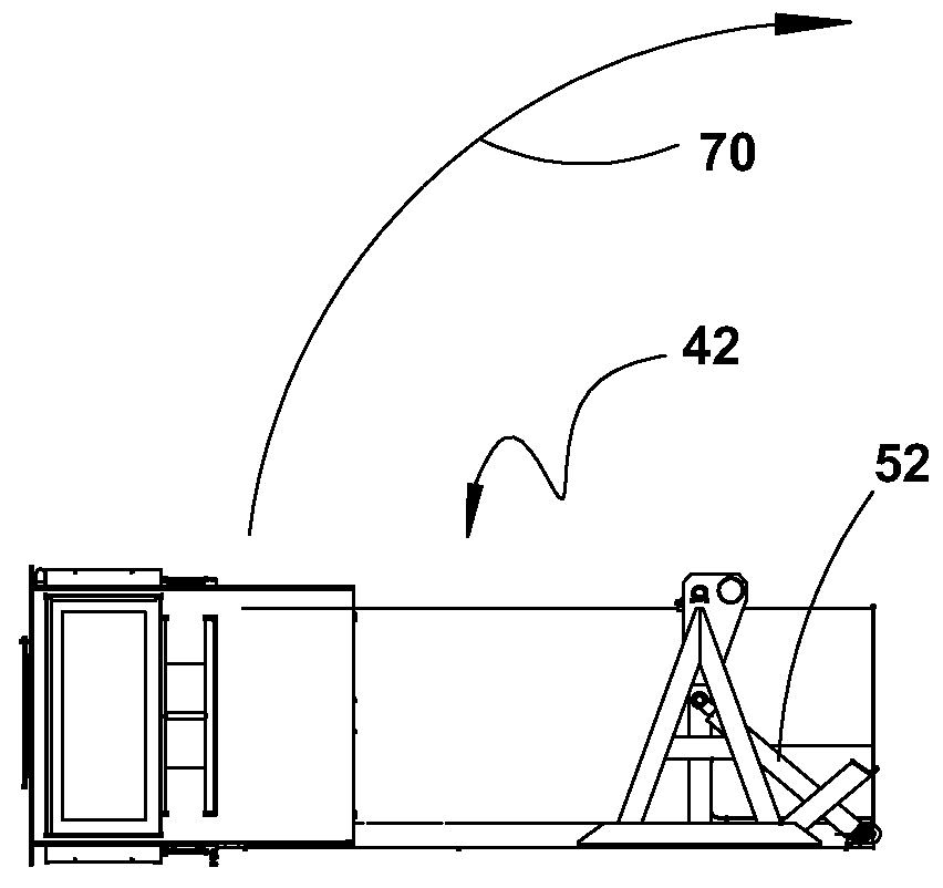
[0007]In accordance with the present invention a deployable and erectable watchtower (DEWT) is provided. The folded watchtower is translocated by haulage by means of a suitable vehicle and deployed by implementing several simple actions performed while still on the vehicle. When the watchtower is in a functional state, the carrying vehicle Is free to move away from the site of deployment.

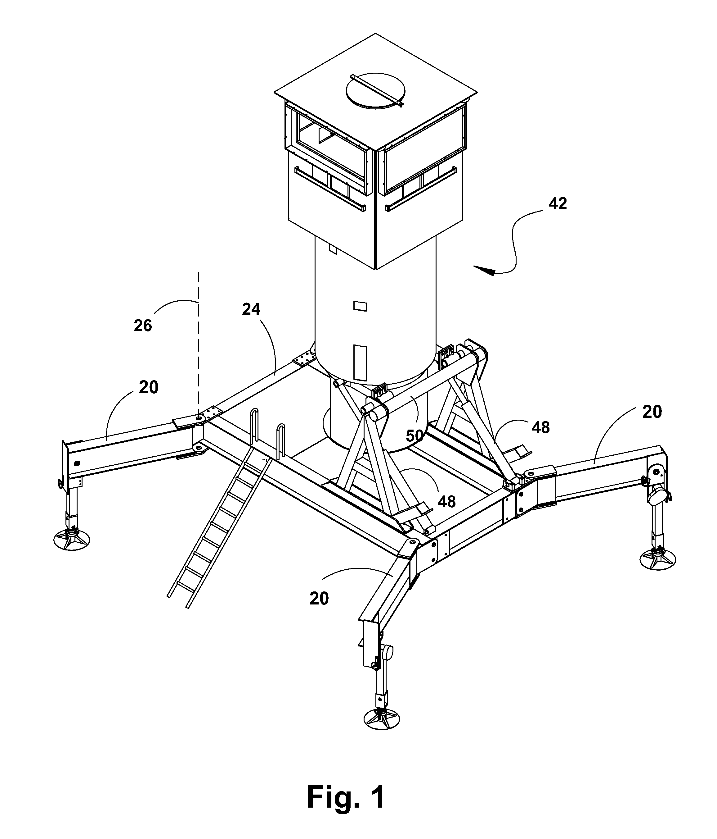
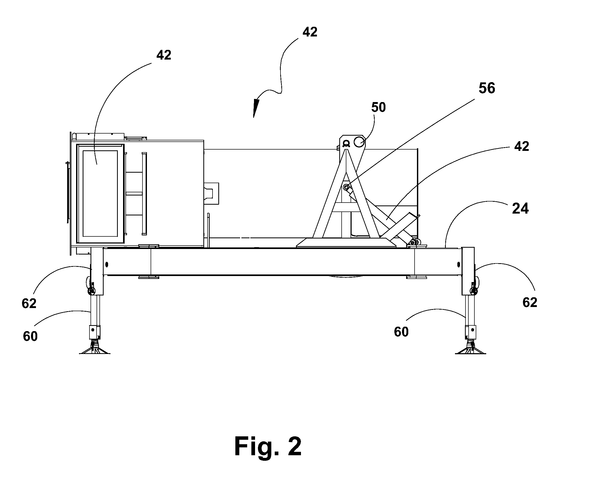
[0008]In an example of a watchtower in accordance with the present invention, as can be seen in FIG. 1 to which reference is now made, the DEWT incorporates prominent features described next. Four sideways foldable support legs (SLs) 20 (only three shown) are all pivotally connected to base frame 24 of the DEWT. The folding pivot facilitates folding of the legs 20 between a contracted position and a deployed position around axis 26. The contracted position allows haulage on a vehicle traveling on roads or off road, with legs contracted, adjacent base frame 24. Erectable unit 42 establishes an uprigh...


PUM


Abstract

A deployable and erectable watch tower for accommodating personnel in an upper chamber thereof is disclosed. The deployable and erectable watch tower is translocatable by haulage and includes an erectable unit; a base frame; a hydraulic actuator for erecting the erectable unit, an upper chamber of the erectable unit having transparent windows and a roof; sideways foldable legs for supporting the base frame on the ground; and ground stilts for supporting the legs on the ground. The deployable and erectable watch tower may further include armoured elements attached at least to the erectable unit.

Description

FIELD OF THE INVENTION[0001]The present invention is in the field of terrestrial defensive measures. More specifically the invention is a watchtower.BACKGROUND OF THE INVENTION[0002]Watching over specified locations is a matter of securing a specific zone or passage, and may be associated with dangerous or even deadly activities. Watchmen in their duty of surveillance or inspection over designated areas may be put into dangerous situations during their duty hours. The well-being of the watchmen is not only an interest of the watchmen themselves but also a matter of the quality of service provided by the personnel.BRIEF DESCRIPTION OF THE DRAWINGS[0003]FIG. 1 is a schematic description of an exemplary watchtower showing main aspects of the invention;[0004]FIG. 2 is a schematic side view description of an exemplary watchtower in a non erected state but with ground stilts protruding;[0005]FIG. 3A is a schematic description of erectable unit in prostrate position.[0006]FIG. 3B is a sche...

Claims


Application Information

Patent Timeline
Patent Type & Authority Applications(United States)
IPC IPC(8): E04H12/34
CPCE04H12/187F41H5/24F41H5/20
Inventor KLEIN, AMOS
Owner KLEIN
Why Eureka
Try Eureka