Multi-output type dc/dc converter

a multi-output type, converter technology, applied in the direction of process and machine control, instruments, packaged goods types, etc., can solve the problems of the difficulty of keeping the desired electric potential, the inability to intercept the signals input, etc., to prevent the output voltage from greatly shifting, and the effect of preventing production

Active Publication Date: 2007-12-13
MITSUMI ELECTRIC CO LTD
View PDF2 Cites 12 Cited by
  • Summary
  • Abstract
  • Description
  • Claims
  • Application Information

AI Technical Summary

Benefits of technology

[0009]An object of the present invention is to provide a multi-output type DC / DC converter that intermittently applies an input voltage to a reactor (inductor) to flow a current and distributes the output from the reactor to a plurality of output terminals by a time division method for outputting a plurality of voltages, the multi-output type DC / DC converter capable of preventing the output voltages from greatly shifting from desired electric potentials owing to changes of loads to output stable direct-current voltages, the multi-output type DC / DC converter preventing the production of an undesirable control state even when the outputs of the comparison circuits provided to the respective plural outputs change almost at the same time.

Problems solved by technology

However, because the multi-output type DC / DC converter of FIG. 8 distributes the output current of the inductor L to the first output terminal OUT1 and the second output terminal OUT2 at a predetermined period (fixed), the multi-output type DC / DC converter has a problem of the difficulty of keeping the desired electric potentials if the current ratio of the loads connected to the two output terminals greatly changes.
However, it became apparent that it was apprehended that, even if the output selection circuit was configured to select the earlier one of the output signals of a plurality of comparison circuits and to intercept the other output signals, when the output signals from a plurality of comparison circuits were input almost at the same time, it was impossible to intercept the signals input later owing to the delay time in the inside of logic circuits and the like, and that the state in which the drive circuits on the subsequent stages did not operate was thereby caused.

Method used


Image

  • Multi-output type dc/dc converter
  • Multi-output type dc/dc converter
  • Multi-output type dc/dc converter

Examples


first embodiment

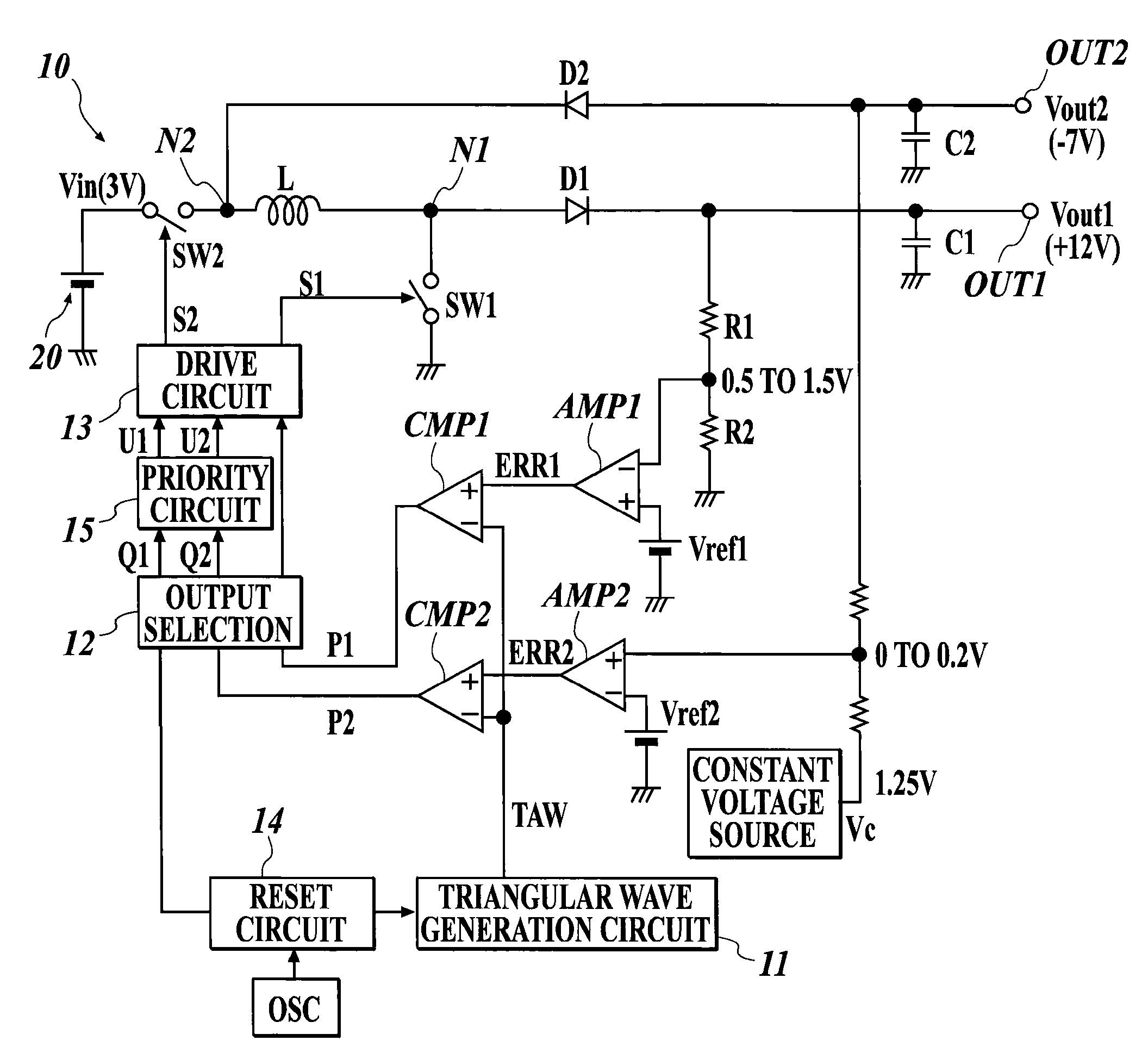
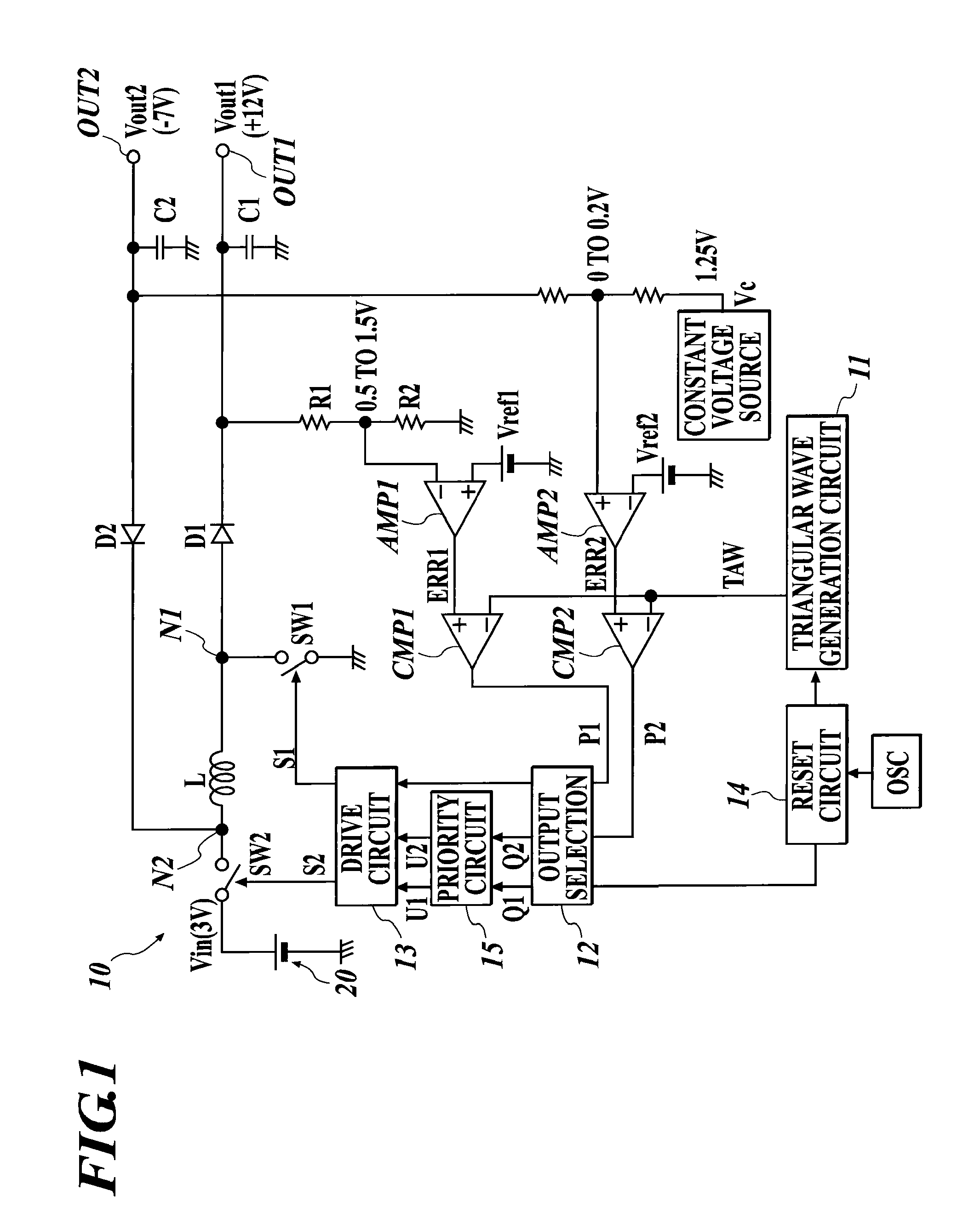
[0042]FIG. 1 is a configuration diagram showing a multi-output type DC / DC converter of the present invention.

[0043]The multi-output type DC / DC converter 10 of the embodiment is a boosting & inverting type converter. The boosting & inverting type converter turns on switches SW1 and SW2, which are constructed of transistors such as a MOSFET, to apply an input voltage Vin from a direct-current power supply 20 to a reactor L for flowing an current therethrough. The boosting & inverting type converter thus applies a current to flow on the output side from the reactor L to perform voltage output. The multi-output type DC / DC converter 10 outputs two kinds of output voltages Vout1 and Vout2 to two output terminals OUT1 and OUT2, respectively, by switching of the switches in the above boosting & inverting type converter.

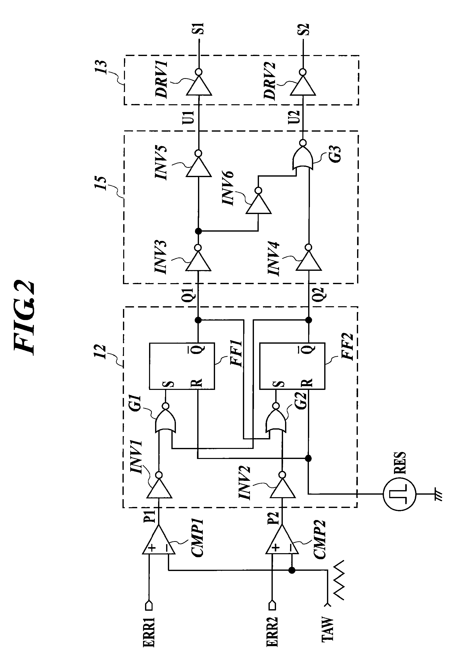
[0044]The multi-output type DC / DC converter 10 of the embodiment includes the reactor L accumulating electric energy, a switch SW2 provided between the direct-current power s...

second embodiment

[0064]FIG. 4 is a configuration diagram showing a multi-output type DC / DC converter of the present invention.

[0065]The multi-output type DC / DC converter 10 of the embodiment is a boosting & boosting type converter including a reactor L, a switch SW0 provided between the reactor L and the ground, which switch SW0 intermittently applies an input voltage Vin to the reactor L by the on-off action of the switch SW0 to accumulate energy in the reactor L, a first rectification & smoothing circuit 16a provided between the reactor L and a first output terminal OUT1, a second rectification & smoothing circuit 16b provided between the reactor L and the second output terminal OUT2, a switch SW1 connected between the reactor L and the first rectification & smoothing circuit 16a, and a switch SW2 connected between the reactor L and a second rectification & smoothing circuit 16b. Furthermore, the multi-output type DC / DC converter 10 includes a first detection circuit 17a detecting a first output v...

third embodiment

[0069]FIG. 5 is a configuration diagram showing a multi-output type DC / DC converter of the present invention.

[0070]The multi-output type DC / DC converter 10 of the embodiment is a boosting & stepping down type converter including a reactor L, a switch SW0 provided between a direct-current power supply 20, and the reactor L and the ground, which switch SW0 intermittently applies an input voltage Vin to the reactor L by the on-off action of the switch SW0 to accumulate energy in the reactor L, a switch SW3 provided between one terminal of the reactor L and the ground, a switch SW4 provided between the other terminal of the reactor L and the ground, a switch SW1 connected between the reactor L and a first rectification & smoothing circuit 16a, and a switch SW2 connected between the reactor L and a second rectification & smoothing circuit 16b.

[0071]The multi-output type DC / DC converter 10 of the embodiment can output a voltage obtained by boosting the input voltage Vin to the output ter...


PUM


Abstract

A multi-output type DC/DC converter including: a reactor connected to a direct-current power supply; a first switching circuit to apply a current to the reactor; a second switching to switch an output from the reactor to any one of output terminals; output voltage detection units to detect voltages of the output terminals; comparison circuits to compare outputs of the output voltage detection units with a waveform signal of a predetermined frequency; and an output selection unit to receive outputs of the comparison circuits as inputs, the output selection unit selecting an output of a comparison circuit, the output having an earlier rise or an earlier fall, to generate a plurality of control signals pertaining to on and off of the first switching circuit and/or the second switching circuit, the output selection unit treating the plurality of control signals in accordance with a predetermined priority order when the outputs of the plurality of comparison circuits change almost at the same time, wherein a current generated by a discharge of energy accumulated in the reactor is output to any one of the output terminals in accordance with the control signals generated by the output selection unit.

Description

BACKGROUND OF THE INVENTION[0001]1. Field of the Invention[0002]The present invention relates to a switching power supply apparatus and a multi-output type DC / DC converter outputting a plurality of voltages from one input voltage, and more particularly to a DC / DC converter provided with a selection circuit and a priority circuit for switching output currents according to the level of each voltage output.[0003]2. Related Art[0004]There is a DC / DC converter as a power supply apparatus converting a direct-current input voltage into a direct-current voltage of an electric potential different from that of the input voltage to output the converted direct-current voltage. Moreover, there is a circuit shown in FIG. 8 as a multi-output type DC / DC converter outputting a plurality of direct-current voltages having different electric potentials to one direct-current input. Such a multi-output DC / DC converter is disclosed in, for example, JP-A 2005-117886.[0005]The DC / DC converter shown in FIG. ...

Claims


Application Information

Patent Timeline
Patent Type & Authority Applications(United States)
IPC IPC(8): G05F1/00
CPCH02M2001/008H02M3/1584H02M1/008
Inventor KUMAGAI, KEIZO
Owner MITSUMI ELECTRIC CO LTD
Why Eureka
Try Eureka