Band gap constant-voltage circuit

a constant-voltage circuit and band gap technology, applied in the direction of electric variable regulation, process and machine control, instruments, etc., can solve the problem of 0 v stability of output voltage, and achieve the effect of preventing the stability of output voltage and quick startup time upon power-on

Inactive Publication Date: 2009-04-07
ABLIC INC
View PDF8 Cites 3 Cited by
  • Summary
  • Abstract
  • Description
  • Claims
  • Application Information

AI Technical Summary

Benefits of technology

[0009]The present invention has been made to solve the above-mentioned problem, and has an object to provide a band gap constant-voltage circuit capable of achieving a quick startup time upon power-on to thereby preventing an output voltage from being stabilized at 0 V due to noise or the like even under the normal condition.
[0011]According to the band gap constant-voltage circuit of the present invention having the above-mentioned configuration, it is possible to achieve a quick startup time upon power-on and to prevent an output voltage from being stabilized at 0 V due to noise or the like even under the normal condition.

Problems solved by technology

However, the conventional band gap constant-voltage circuit shown in FIG. 2 is slow in startup upon power-on, and therefore has a drawback in that the output voltage is stabilized at 0 V due to noise or the like even under the normal condition.

Method used


Image

  • Band gap constant-voltage circuit
  • Band gap constant-voltage circuit
  • Band gap constant-voltage circuit

Examples


Embodiment Construction

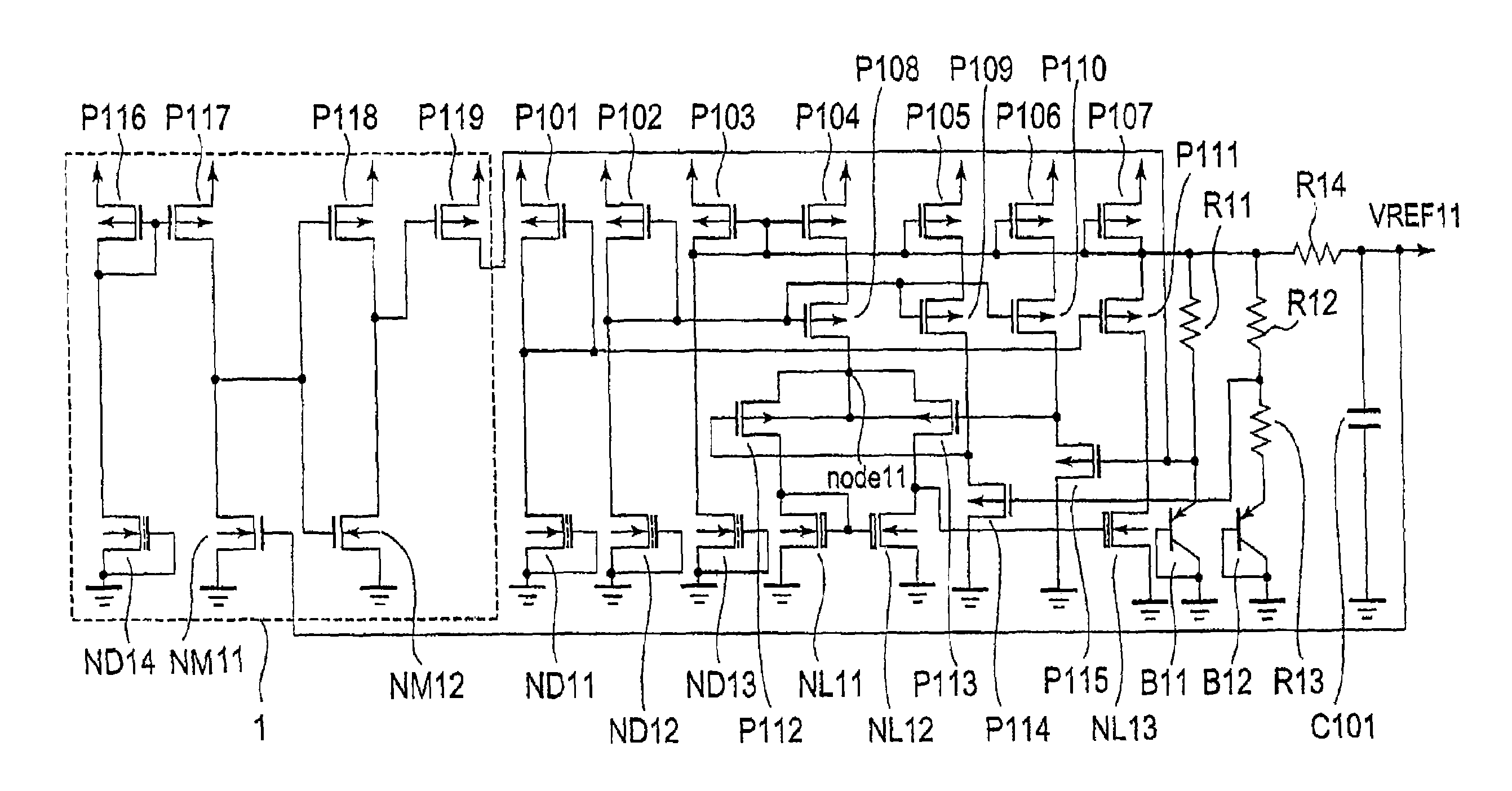
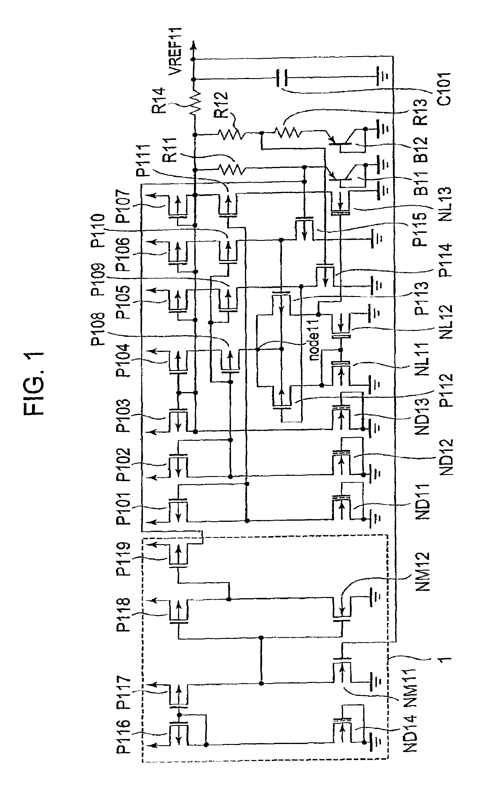
[0015]FIG. 1 is a circuit diagram showing a band gap constant-voltage circuit according to the present invention.

[0016]As shown in FIG. 1, the band gap constant-voltage circuit includes a differential amplifier, a level shifter circuit connected to an input of the differential amplifier, and a constant-voltage circuit.

[0017]The differential amplifier of the band gap constant-voltage circuit is constituted of a pair of p-channel type transistors P112 and P113, n-channel type transistors NL11 and NL12, the n-channel type transistors NL11 and NL12 each having a low threshold value (of, for example, 0.45 V). (Hereinafter, n-channel type transistor is abbreviated as n-type transistor, and p-channel type transistor is abbreviated as p-type transistor.)

[0018]The source of the n-type transistor NL11 is connected to a ground which serves as a reference potential, while the drain thereof is connected to the drain of the p-type transistor P112. Also, the gate of the n-type transistor NL11 is c...


PUM


Abstract

Provided is a band gap constant-voltage circuit capable of achieving a quick startup time to thereby preventing an output voltage from being stabilized at 0 V due to noise or the like even under the normal condition. The band gap constant-voltage circuit according to the present invention includes: an output voltage detecting circuit for monitoring a voltage at an output terminal; and a current source which has a current value controlled through an output of the output voltage detecting circuit, in which the current source supplies a bipolar transistor constituting a level shifter circuit with a current when the voltage at the output terminal is lower than a predetermined voltage.

Description

[0001]This application claims priority under 35 U.S.C. §119 to Japanese Patent Application No. JP2006-041690 filed Feb. 18, 2006, the entire content of which is hereby incorporated by reference.BACKGROUND OF THE INVENTION[0002]1. Field of the Invention[0003]The present invention relates to a band gap constant-voltage circuit, in particular, a startup circuit capable of securely outputting an output voltage upon power-up to thereby achieve a quick startup time.[0004]2. Description of the Related Art[0005]FIG. 2 is a circuit diagram of a conventional band gap constant-voltage circuit. The voltage circuit is constituted of PMOS transistors P21, P22, P23, P24, and P25, NMOS transistors NL21, NL22, and NL23, an n-channel type depression transistor ND21, bipolar transistors B21 and B22, and resistors R21, R22, R23, and R24, and capacitor C21. In FIG. 2, when a ratio of the number of the bipolar transistor B21 provided as a first bipolar transistor to that of the bipolar transistor B22 pro...

Claims


Application Information

Patent Timeline
Patent Type & Authority Patents(United States)
IPC IPC(8): G05F1/10
CPCG05F3/30G05F3/26
Inventor UEHARA, OSAMU
Owner ABLIC INC
Why Eureka
Try Eureka