
Cathode for cathode-ray tube having high current density and long life

a cathode and cathode technology, applied in the direction of discharge tube/lamp details, discharge tube main electrodes, discharge tube solid thermionic cathodes, etc., can solve the problems of deterioration of the isolation of the heater 124, deformation of the sleeves 123, and difficulty in welding the whole bottom surface of the cups, etc., to achieve high current density

Inactive Publication Date: 2002-09-12
NEC ELECTRONICS CORP
View PDF5 Cites 11 Cited by
  • Summary
  • Abstract
  • Description
  • Claims
  • Application Information

AI Technical Summary

Benefits of technology

[0010] Therefore, it is an object of the present invention to provide a cathode for a cathode-ray tube which cathode has a high current density and a long life and which can be mass-produced.
[0011] It is another object of the present invention to provide a cathode for a cathode-ray tube which cathode can be mass-produced without causing temperature dispersion of a cathode pellet.
[0012] It is still another object of the present invention to provide a cathode for a cathode-ray tube which cathode has a high current density and a fast startup time.

Problems solved by technology

However, when the temperature of the heater 124 is high, there is a possibility that the sleeve 123 deforms, isolation of the heater 124 deteriorates, and the like.
However, it is difficult to weld the whole bottom surface of the cup 122 with the cathode pellet 121.
However, in such method, there is a possibility that the temperature of the whole cathode pellet 121 rises and the electron emission agent decomposes.
Therefore, such method is not applicable.

Method used


Image

  • Cathode for cathode-ray tube having high current density and long life
  • Cathode for cathode-ray tube having high current density and long life
  • Cathode for cathode-ray tube having high current density and long life

Examples


Embodiment Construction

[0057] With reference to the drawings, a description will be made on embodiments of the present invention. In the following description, the n-th power of 10, i.e., 10.sup.n, is represented by 10 En, and the (-n)-th power of 10, i.e., 10.sup.-n, is represented by 10 E-n.

[0058] In an embodiment of the present invention, first, 100 grams of nickel powder having an average particle size of 5 .mu.m, 6 grams of scandium oxide, and 60 grams of coprecipitated carbon salt of barium-strontium-calcium having an average particle size of 1-2 .mu.m were uniformly mixed in a dry type mixer. The component mole ratio of the coprecipitated carbon salt is (barium:strontium:calcium)=(50:40:10). Among these, coprecipitated carbon salt of barium-strontium-calcium becomes an electron emission agent.

[0059] The above-mentioned mixed powder was press worked at room temperature and a cylindrical molded body was fabricated. At this stage, nickel powder was not yet sintered.

[0060] The molded body formed as abo...


PUM


Abstract

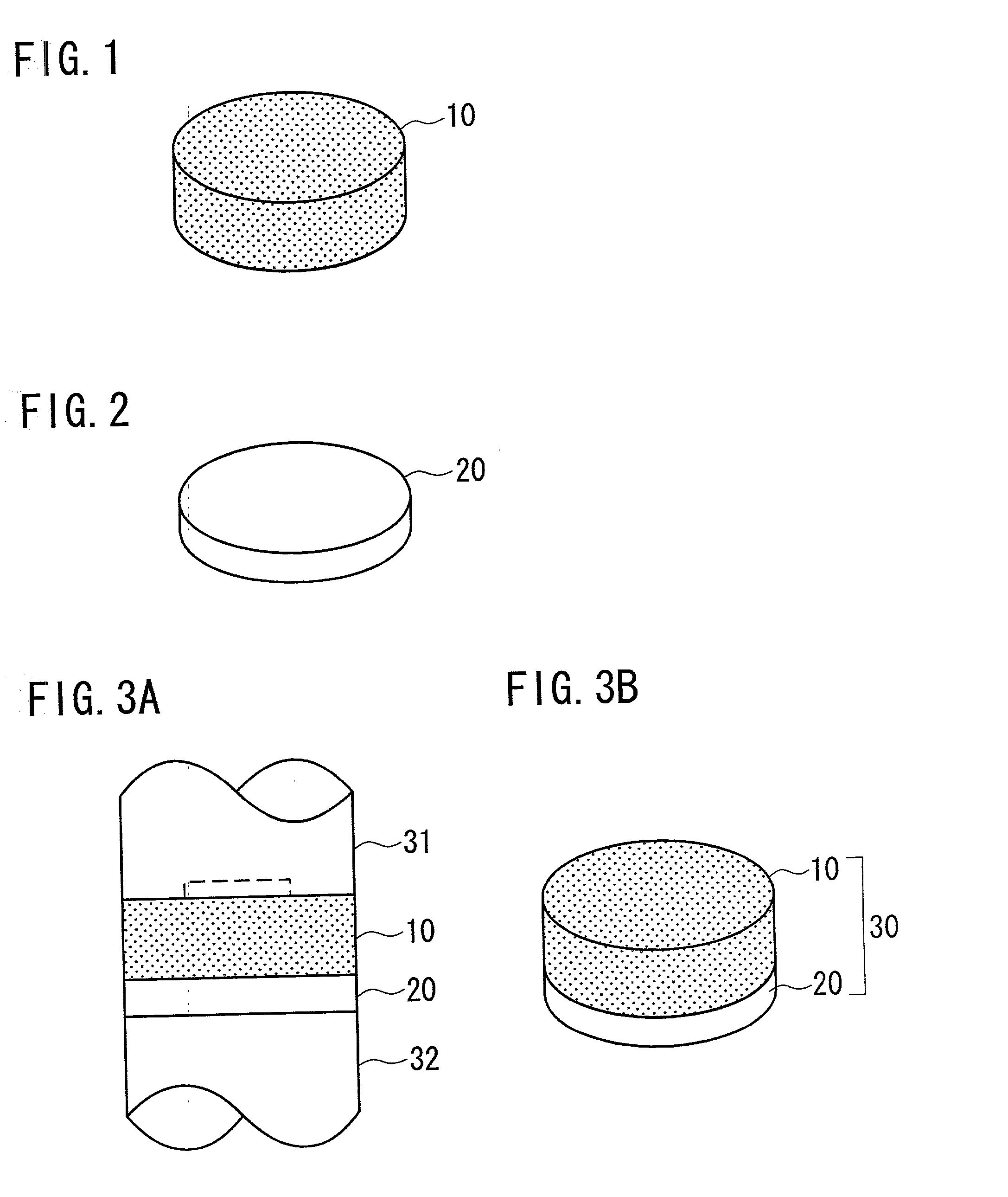
A cathode for a cathode-ray tube which has high current density and long life and which can be mass-produced without dispersion of a cathode pellet temperature. The cathode comprises a cathode pellet formed from a sintered body which is obtained by sintering a mixture containing at least a nickel powder and a powder of electron emission agent by hot isostatic pressing. The cathode also comprises a cathode pellet support member on which the cathode pellet is attached. According to the present invention, the cathode pellet support member is a bottom plate which covers only a bottom surface of the cathode pellet. The cathode pellet may have a column shape, and the bottom plate may have a disk shape or a reversed cup shape.

Description

FIELD OF THE INVENTION[0001] The present invention relates generally to a cathode for a cathode-ray tube, a cathode-ray tube, and a method of manufacturing them. More particularly, the present invention relates to a cathode for a cathode-ray tube, for example, a color cathode-ray tube which has high current density and long life and which can be mass-produced without dispersion of a cathode pellet temperature.BACKGROUND OF THE INVENTION[0002] In Japanese patent laid-open publication No. 2001-006521, the inventor of the present invention proposed a new structure of a cathode which obviates a problem of rapid reduction of electron emission at high current density. FIG. 12 is a partially cut away perspective view illustrating such cathode as a conventional cathode 120. An explanation will be made on the conventional cathode 120 and a manufacturing method thereof.[0003] First, nickel powder, scandium oxide powder and electron emission agent are mixed and sintered by a hot isostatic pres...

Claims


Application Information

Patent Timeline
IPC IPC(8): H01J1/28H01J1/14H01J1/26H01J9/04H01J29/04
CPCH01J1/14H01J9/04
Inventor SUGIMURA, TOSHIKAZUTANAKA, YOSHIYUKI
Owner NEC ELECTRONICS CORP
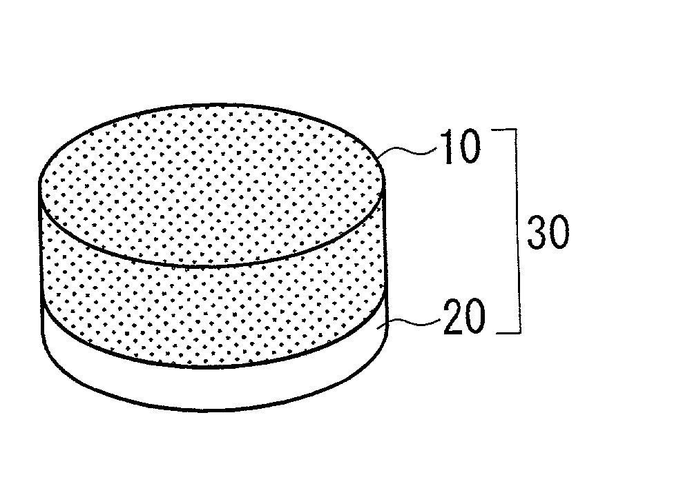
Learn More