Control Method During Zero-Crossing Operation Of Bridge Arms In UPS

a control method and bridge arm technology, applied in emergency power supply arrangements, climate sustainability, energy industry, etc., can solve the error of zero-crossing synchronization between the pfc circuit and the inverter circuit, and the power consumption thereon is small, so as to reduce the influence and achieve simple and easy implementation

Inactive Publication Date: 2014-04-17
VERTIV CORP
View PDF3 Cites 3 Cited by
  • Summary
  • Abstract
  • Description
  • Claims
  • Application Information

AI Technical Summary

Benefits of technology

[0013]Important advantages of the present invention in comparison with the prior art are that the control method, during bridge arm operation in a UPS, and when zero-crossing switching, controls the midline bridge arm and the rectifying bridge arm to operate synchronously, and at the same time controls the inverter bridge arm to stop operating, and turns off the switching transistors that forms the UPS output voltage oscillating loop in the inverter bridge arm. This may avoid the UPS output voltage oscillating caused by asynchronous zero-crossing of the midline bridge arm and the inverter bridge arm, thereby effectively reducing the influence of above-mentioned asynchrony on the UPS performance index THDv. On the other hand, when zero-crossing switching, the method controls the midline bridge arm and the inverter bridge arm to operate synchronously, and at the same time controls the rectifying bridge arm to stop operating, and disconnects the switching transistor that forms the UPS output voltage oscillating loop in the rectifying bridge arm. This may avoid the UPS output voltage oscillating causing by asynchronous zero-crossing of the rectifying bridge arm and the midline bridge arm, thereby effectively reducing the influence of the above mentioned asynchrony on the UPS performance index THDi. The method of the present invention forces the switching transistors in the bridge arms causing oscillating nearby the zero-crossing to be turned off, which is simple and easy to implement, and may effectively reduce the influence of the asynchronous zero-crossing switch of the inverter circuit and the PFC circuit on the UPS performance indices.

Problems solved by technology

Thus the power consumption thereon is small as well.
Otherwise, the circuit cannot operate normally.
However, due to different zero-crossing switching modes of the PFC circuit and the inverter circuit or the errors in phase-locking and in the controlled quantity, there will be error of zero-crossing synchronization between the PFC circuit and the inverter circuit.

Method used


Image

  • Control Method During Zero-Crossing Operation Of Bridge Arms In UPS
  • Control Method During Zero-Crossing Operation Of Bridge Arms In UPS
  • Control Method During Zero-Crossing Operation Of Bridge Arms In UPS

Examples


embodiment 1

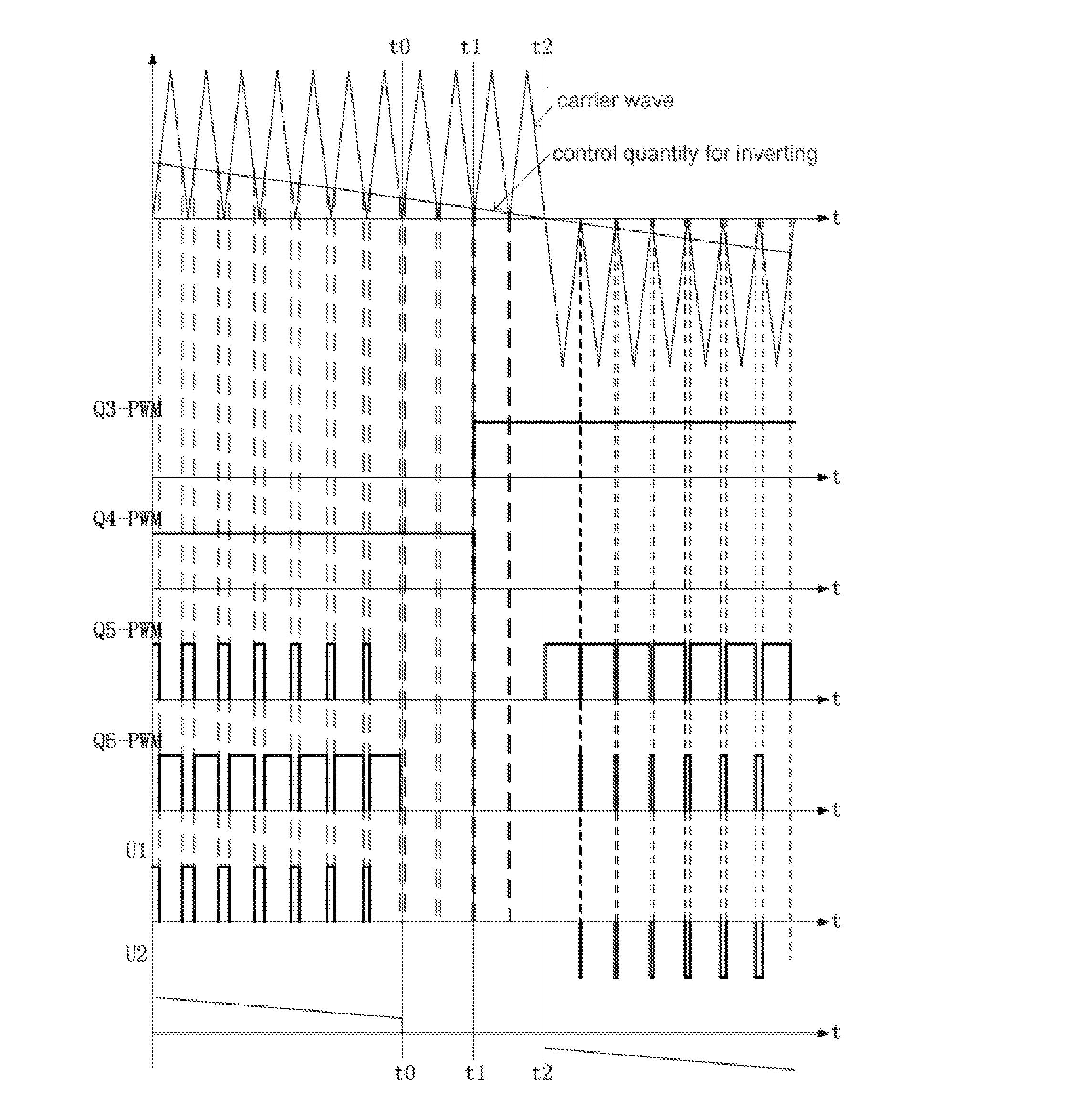
[0031]The schematic waveform of the control signal in this embodiment is shown in FIG. 2. The waveforms Q3-PWM, Q4-PWM, Q5-PWM, and Q6-PWM correspond to the driving signals of the third switching transistor Q3, the fourth switching transistor Q4, the fifth switching transistor Q5 and the sixth switching transistor Q6, respectively. The waveform labeled U1 is a pulse-width modulation voltage outputted by an inverter bridge arm. A desired sine waveform voltage U2 is obtained after being filtered by an inductance L2 and a capacitance C2. Time t1 is the zero-crossing point of the PFC circuit from the positive half cycle to the negative half cycle. Due to the synchronization error the zero-crossing point of the inverter circuit from the positive half cycle to the negative half cycle is different from the zero-crossing point of the PFC circuit from the positive half cycle to the negative half cycle, and the time differences in various cycles may be different but the time difference betwee...

embodiment 2

[0036]The difference between the present embodiment and the embodiment 1 is that the present embodiment is the control of the rectifying bridge arm from the negative half cycle to the positive half cycle, while embodiment 1 is the control of the rectifying bridge arm from the positive half cycle to the negative half cycle.

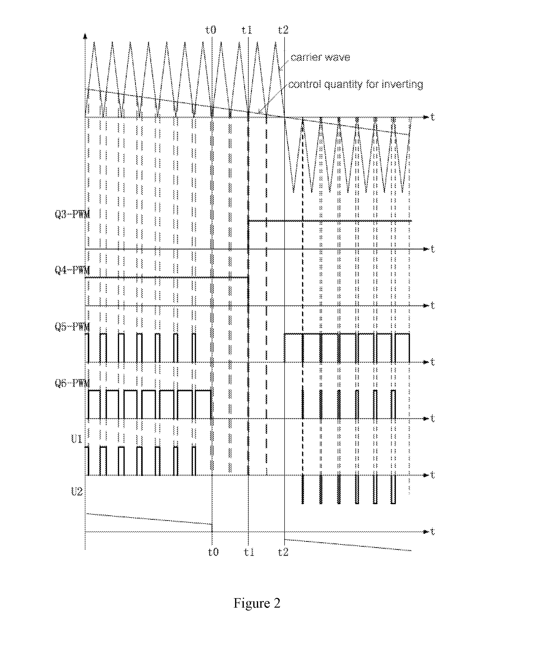
[0037]The schematic waveform of the control signal in this embodiment is shown in FIG. 4. Waveforms Q3-PWM, Q4-PWM, Q5-PWM, and Q6-PWM correspond to the driving signals of the third switching transistor Q3, the fourth switching transistor Q4, the fifth switching transistor Q5 and the sixth switching transistor Q6, respectively. Waveform U1 is a pulse-width modulation voltage outputted by an inverter bridge arm, which is filtered by an inductance L2 and a capacitance C2 to produce a desired sine waveform U2. Time t4 is the zero-crossing point of the PFC circuit from the negative half cycle to the positive half cycle. Because of the synchronization error, the zero-cr...

embodiment 3

[0041]The difference between the present embodiment and the preceding two embodiments is that the present embodiment controls the midline bridge arm and the inverter bridge arm to cross zero synchronously, and disconnects the rectifying bridge arm during a period before and after zero-crossing of the inverter. The preceding two embodiments, however, control the midline bridge arm and the rectifying bridge arm to cross zero synchronously and disconnect the inverter bridge arm during a period before and after zero-crossing of the rectifying bridge arm.

[0042]FIG. 6 is the schematic waveform of the control signal in the present embodiment. As shown in FIG. 6, Q1-PWM, Q2-PWM, Q3-PWM, and Q4-PWM correspond to the driving signals of the first switching transistor Q1, the second switching transistor Q2, the third switching transistor Q3, and the fourth switching transistor Q4, respectively. The IL waveform is the current on the inductance L1. Time t7 is the zero-crossing point of the invert...


PUM


Abstract

A control method is disclosed that involves controlling zero-crossing operation of bridge arms in a UPS, wherein the UPS has a rectifying bridge with first and second switching transistors, a midline bridge arm with third and fourth switching transitors, and an inverter bridge arm with fifth and sixth switching transitors. The midline and rectifying bridge arms are controlled to cross zero synchronously. The inverter bridge arm is controlled to be disconnected during a period before a zero-crossing point of the rectifying bridge arm to a period after the zero-crossing point of the rectifying bridge arm. The periods before and after the zero-crossing point of the rectifying bridge arm are time differences between the zero-crossing points of the inverter bridge arm and the rectifying bridge arm. The influence of asynchronous zero-crossing between the PFC circuit and the inverter circuit on the UPS performance indices may be reduced by using the present control method.

Description

CROSS-REFERENCE TO RELATED APPLICATIONS[0001]This application is a U.S. National Stage Application of International Application No. PCT / CN2011 / 075472, filed Jun. 8, 2011. This application claims the benefit and priority to Chinese Application No. 201010262498.0, filed Aug. 25, 2010. The disclosures of the above applications are incorporated herein by reference.TECHNICAL FIELD[0002]The present invention relates to a control method for an uninterruptible power supply (UPS), and more particularly, to a control method during zero-crossing operation of bridge arms in a UPS.BACKGROUND ART[0003]In the existing uninterruptible power supply, the main circuit topology thereof is shown in FIG. 1. As shown in FIG. 1, an inductance L1, a first switching transistor Q1, a second switching transistor Q2, a body diode of a third switching transistor Q3, and a body diode of a fourth switching transistor Q4 constitute a power factor correction (PFC) circuit. The third switching transistor Q3, the four...

Claims


Application Information

Patent Timeline
Patent Type & Authority Applications(United States)
IPC IPC(8): H02M5/458
CPCH02M5/4585H02J9/062H02J9/063Y02P80/10
Inventor LI, JUNLINFAN, XIAOBOZHANG, YANQUANXIE, LIHUA
Owner VERTIV CORP
Why Eureka
Try Eureka