
Apparatus for sealing and isolating pipelines

a technology for isolating pipelines and apparatuses, which is applied in mechanical apparatus, pipe elements, pipes/joints/fittings, etc., can solve the problems of time-consuming and expensive conventional methods, and does not act as a permanent repair devi

Active Publication Date: 2007-12-13
HALLIBURTON ENERGY SERVICES INC
View PDF12 Cites 28 Cited by
  • Summary
  • Abstract
  • Description
  • Claims
  • Application Information

AI Technical Summary

Benefits of technology

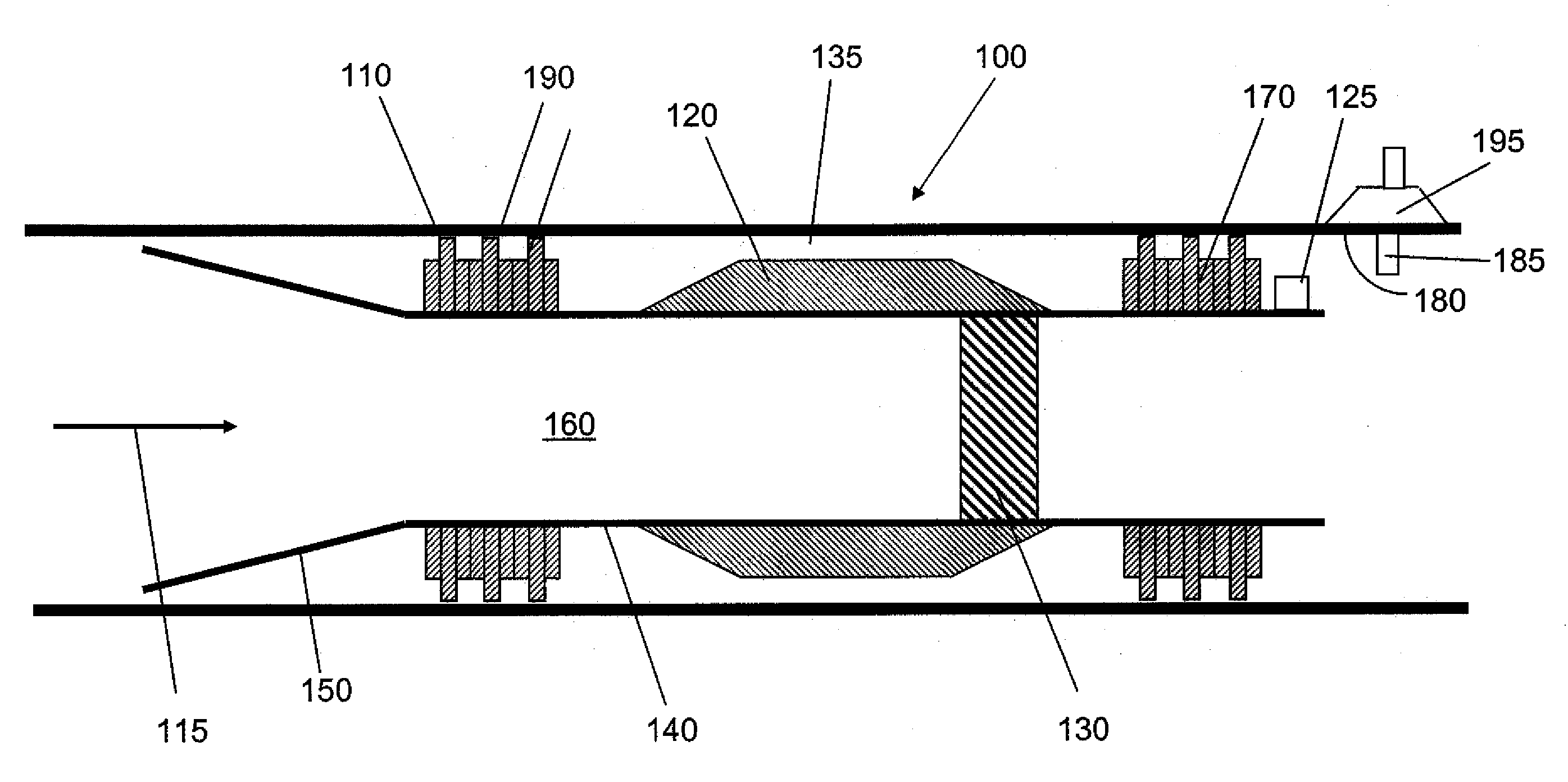
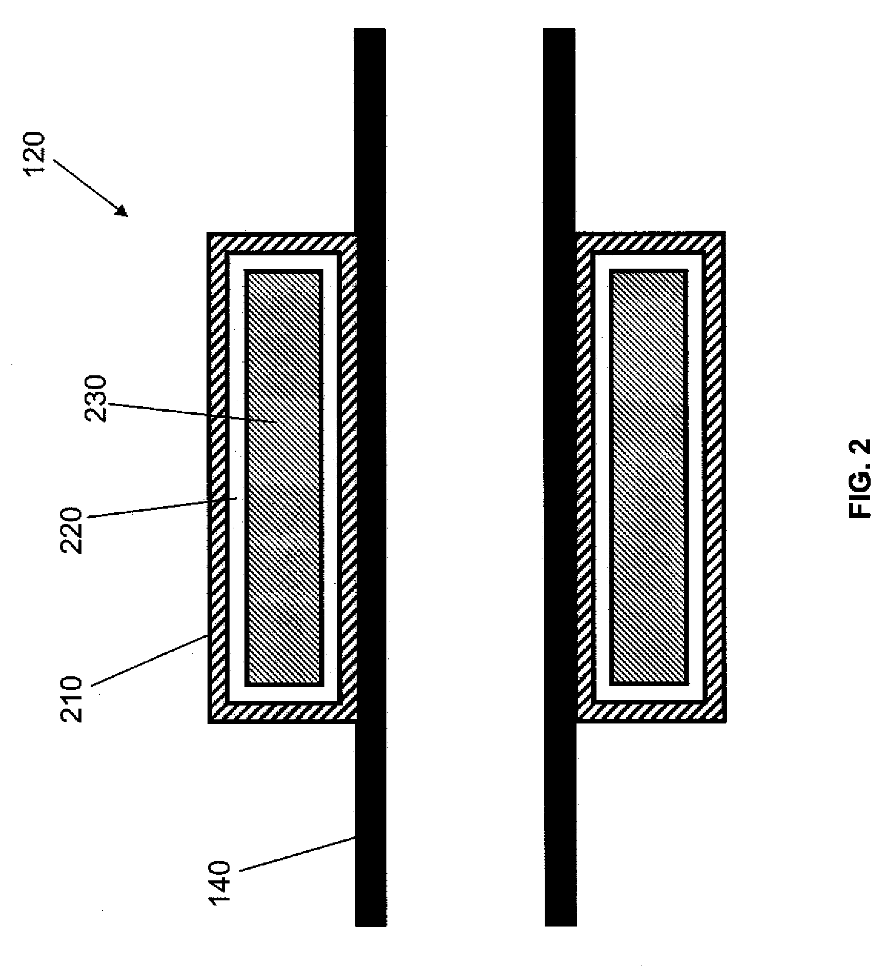
[0010]The pipeline tool may further comprise a plurality of guide cups attached to the tool body that engage the pipeline when the tool is disposed therein. The swellable component disposed about the tool body may comprise a material that expands when exposed to a fluid within the pipeline. In an embodiment, the swellable component comprises a core portion, and the core portion may comprise an elastic polymer selected from the group consisting of EPDM, styrene-butadiene rubber, natural rubber, ethylene-propylene monomer rubber, ethylene-vinyl acetate rubber, hydrogenated acrylonitrile-butadiene rubber, acrylonitrile-butadiene rubber, isoprene rubber, chloroprene rubber and polynorbornene. In another embodiment, the core portion comprises a rubber mechanically mixed with a polymer se

Problems solved by technology

These conventional methods are both time-consuming and expensive due to the discontinued pipeline operations, the loss of product that may be incurred due to draining or blowing down, and the time and expense associated with cutting into the pipeline to make the actual repair and / or perform the maintenance operation, such as replacing a leaking section of pipeline or installing a permanent device.
Drawbacks to the pipeline isolation pig is that it does not act as a permanent repair device, and it does not permit product flow therethrough.

Method used


Image

  • Apparatus for sealing and isolating pipelines
  • Apparatus for sealing and isolating pipelines
  • Apparatus for sealing and isolating pipelines

Examples


Embodiment Construction

[0021]Various embodiments of a pipeline sealing and isolation tool operable to provide a seal within a pipeline for various purposes, including pipeline maintenance, leak repair, and installing permanent devices within the pipeline, will now be described with reference to the accompanying drawings, wherein like reference numerals are used for like features throughout the several views. There are shown in the drawings, and herein will be described in detail, specific embodiments of the pipeline tool with the understanding that this disclosure is representative only and is not intended to limit the invention to those embodiments illustrated and described herein. The embodiments of the pipeline tool and methods disclosed herein may be used in any type of application, operation, or process where it is desired to perform maintenance, repair, and / or installation of permanent devices in a pipeline. It is to be fully recognized that the different teachings of the embodiments disclosed herei...


PUM


Abstract

A pipeline tool for use within a pipeline comprises a tool body with an internal flow bore, a swellable component disposed about the tool body, and a temporary seal disposed internally of the flow bore. The pipeline tool may further comprise a tracking device attached to the tool body, wherein the tracking device comprises a mechanical fixture, or an emitter that emits a signal that can be tracked.

Description

CROSS-REFERENCE TO RELATED APPLICATIONS[0001]None.STATEMENT REGARDING FEDERALLY SPONSORED RESEARCH OR DEVELOPMENT[0002]Not applicable.REFERENCE TO A MICROFICHE APPENDIX[0003]Not applicable.FIELD OF THE INVENTION[0004]The present invention relates generally to apparatus and methods for sealing and isolating pipelines. More particularly, the present invention relates to various embodiments of a pipeline sealing and isolation tool that permits sealing of an :annular area within a pipeline using a swellable component, and temporary sealing of a flowbore through the tool using a temporary internal seal. Still more particularly, the present invention relates to methods of sealing and isolating a pipeline to perform maintenance, seal leaks, or install permanent devices within the pipeline.BACKGROUND[0005]Conventional pipeline maintenance and repair methods comprise first discontinuing normal pipeline operations, then isolating the section of pipeline to be repaired or maintained by closing...

Claims


Application Information

Patent Timeline
IPC IPC(8): F16L55/18
CPCF16L55/132F16L55/48F16L55/26
Inventor FREYER, RUNEABNEY, LAURENCEARRINGTON, STEVE
Owner HALLIBURTON ENERGY SERVICES INC
Learn More