Crop feed arrangement for the header of a combine harvester

a harvester and combine technology, applied in the field of headers of combine harvesters, can solve the problem of not disclosing the construction of these devices in patents

Active Publication Date: 2008-01-31
MACDON INDS
View PDF17 Cites 37 Cited by
  • Summary
  • Abstract
  • Description
  • Claims
  • Application Information

AI Technical Summary

Benefits of technology

[0020]the pan member having a front edge carried on a spring coupling arrangement which allows upward and downward flexing movement of the front edge of the pan member relative to the front guide roller.

Problems solved by technology

Further commercial devices are manufactured by Deere and Company and AGCO but it is believed that there are no patents disclosing the construction of these devices.

Method used


Image

  • Crop feed arrangement for the header of a combine harvester
  • Crop feed arrangement for the header of a combine harvester
  • Crop feed arrangement for the header of a combine harvester

Examples


Embodiment Construction

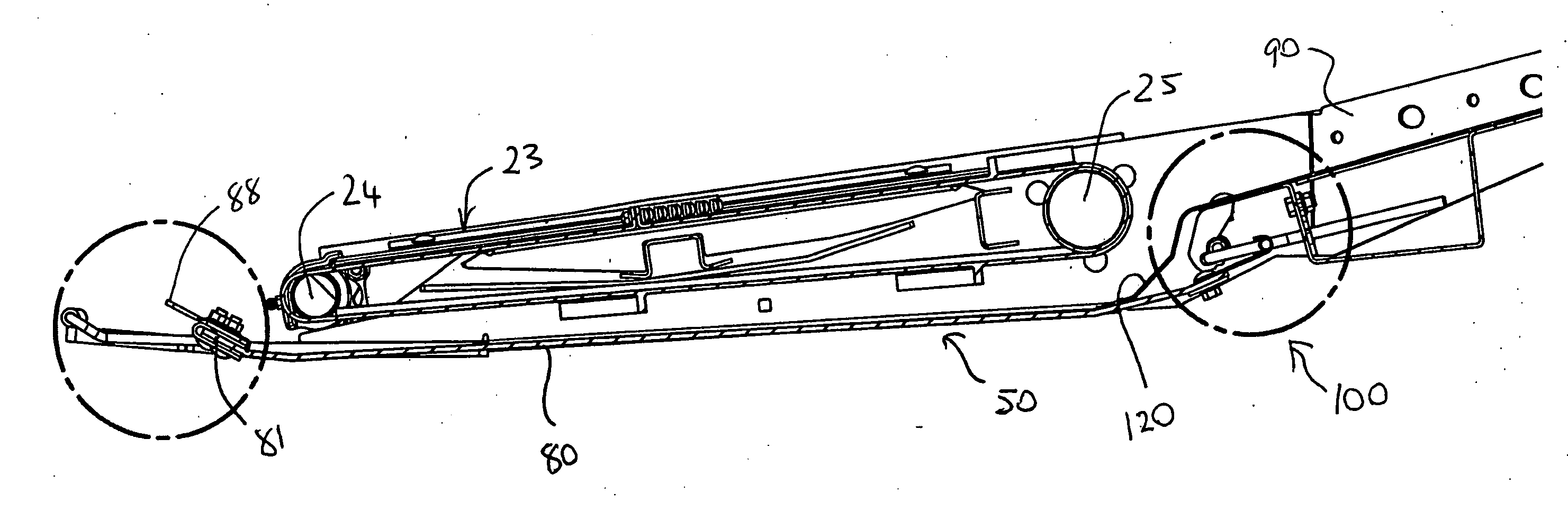
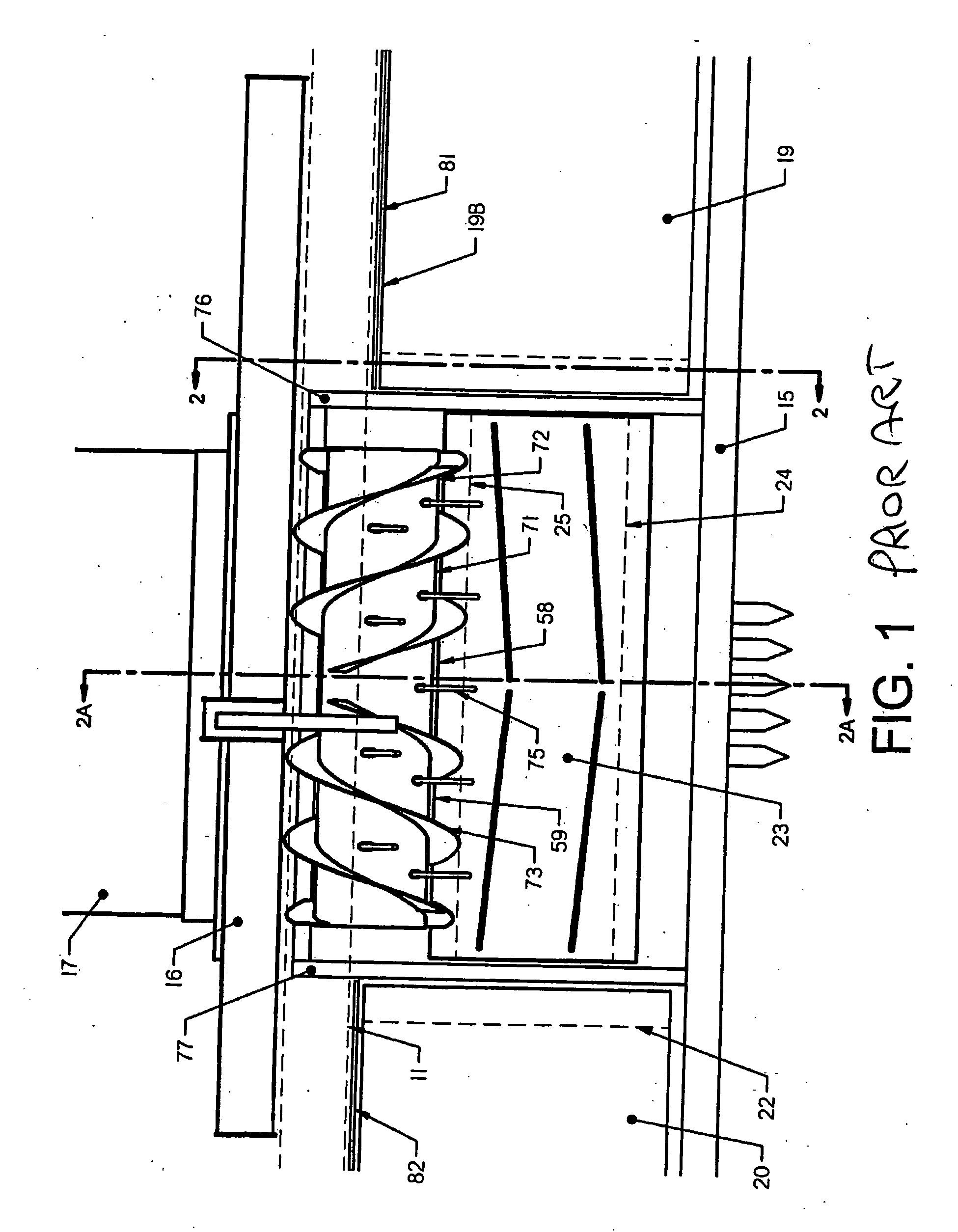
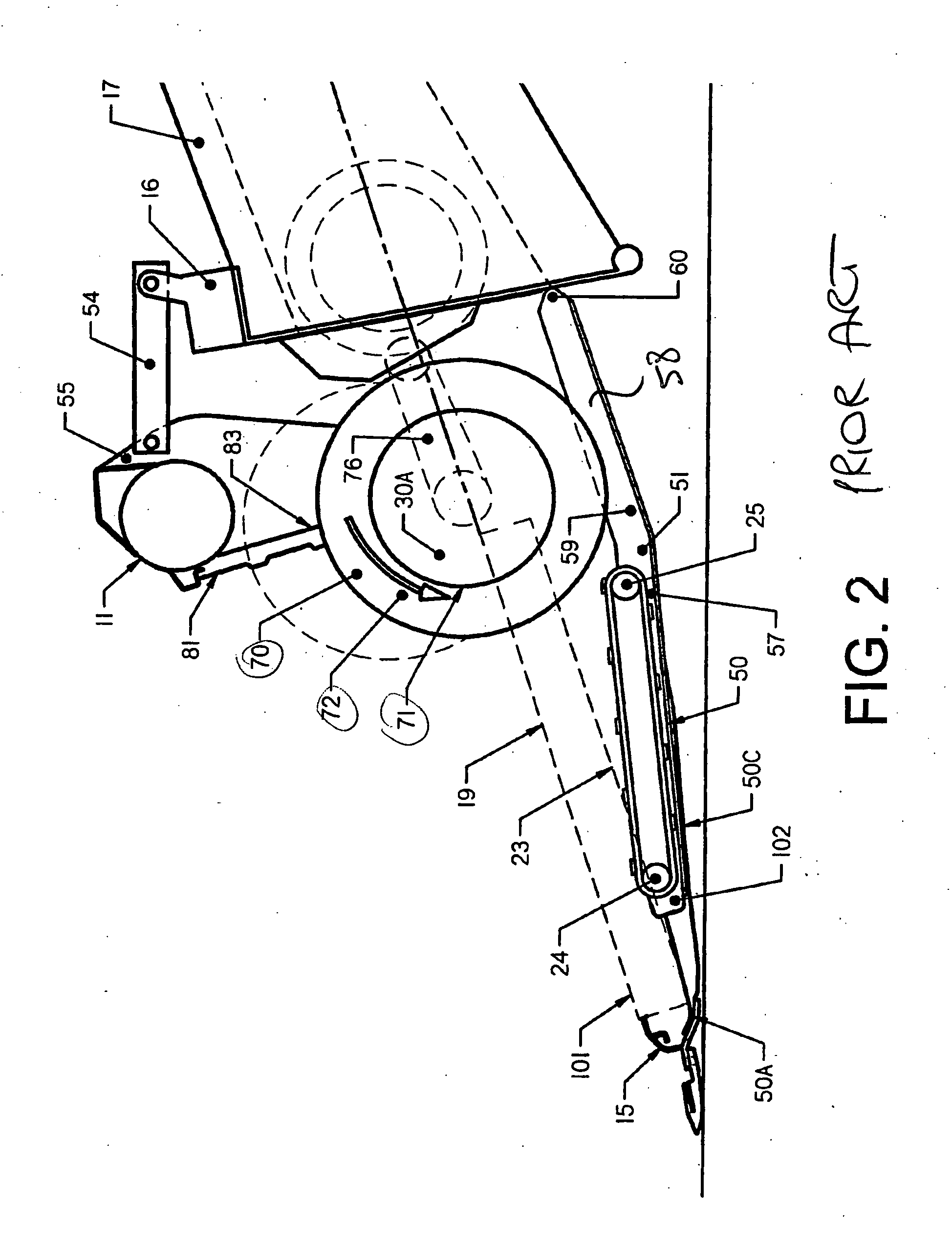
[0082]The PRIOR ART header shown in FIGS. 1 and 2 is taken from U.S. Pat. No. 6,865,871 identified above and is included to show one example of the type of header with which the present invention is primarily concerned, although it will be appreciated that the present invention can be used with headers of different design but including the same general parts as defined hereinafter. The header comprises a main frame 10 including a horizontal main support beam 11 extending along the length of the header along a first end to a second end of the header. The main frame includes forwardly extending frame members (not shown) at the ends together with similarly arranged frame members intermediate the width of the header. At the front end of the frame members is mounted a cutter bar 15 which carries a sickle knife construction of a conventional nature. The frame 10 is attached to an adapter structure 16 attached to the feeder house 17 of a combine harvester.

[0083]The header includes a crop t...


PUM


Abstract

A draper header for a combine harvester includes two side drapers each running from an outer end guide roller at a first end of the header to an inner end guide roller adjacent the discharge location of the header and a central feed draper located at the discharge location and including a front guide roller just behind the cutter bar and running to a rear guide roller in front of the feeder house of the combine harvester. An auger is located between the discharge rollers with a front edge of the flight forward of the rear end of the discharge rollers to feed the material inwardly and underneath the auger to the inlet of the feeder house. A pan member is located underneath the feed draper and is formed of a flexible polyethylene sheet which is tensioned between its front and rear edges by a front mounting strip which is spring mounted for up and down movement and a rear latch which can be released to allow the rear edge to be lowered.

Description

[0001]This invention relates to a crop feed arrangement for the header of a combine harvester.BACKGROUND OF THE INVENTION[0002]A header for a crop harvesting machine generally comprises a main longitudinal support member in the form of an elongate tube which extends across substantially the full width of the header frame and defines a main structural member for the header frame. The tube carries a plurality of forwardly and downwardly extending support beams which include a first portion extending downwardly and a second portion attached to a lower end of the first portion and extending forwardly therefrom toward a forward end of the support beams. The cutter bar is attached to the forward end of the support beams and is thus held thereby in a position generally parallel to the main support tube.[0003]In U.S. Pat. No. 4,956,966 issued September 1990 and U.S. Pat. No. 5,005,343 issued April 1991 and U.S. Pat. No. 6,865,871 issued Mar. 15th, 2005 by Patterson and U.S. Pat. No. 6,817,1...

Claims


Application Information

Patent Timeline
Patent Type & Authority Applications(United States)
IPC IPC(8): A01D34/00
CPCA01D57/20A01D41/14
Inventor PATTERSON, ROGER L.MACDONALD, CHRISTOPHERENNS, JOHN EDWARD
Owner MACDON INDS
Why Eureka
Try Eureka