Food cooking container including a thermal indicator

a technology of food cooking container and thermal indicator, which is applied in the direction of cooking vessel materials, kitchen equipment, domestic applications, etc., can solve the problems of inevitably increasing the cost of end products, requiring specially designed handles, and unable to meet the requirements of use,

Inactive Publication Date: 2008-01-31
BALLARINI PAOLO E FILI SPA
View PDF3 Cites 65 Cited by
  • Summary
  • Abstract
  • Description
  • Claims
  • Application Information

AI Technical Summary

Benefits of technology

[0011]Thus, owing to the provision of the above device, it is possible to form in the food cooking container handle an opening which can be made in a simple manner and independently from the shape of the handle. In this temperature measurement opening, is engaged an envelope, advantageously made of a metal sheet material, having a bottom lug which is locked, by the handle clamping screw thereby transmitting heat from the cooking container to the envelope so that, by introducing the measurement stem, having a sensor including region, it would be possible to provide temperature indicating signals, indicating the temperature in the food cooking container.

Problems solved by technology

Prior food cooking container temperature signaling systems, however, have the drawback that, as they comprise thermochromatic dies or pigments, the latter, because of a repeated cleansing of the containers, loose their indicating efficiency.
Yet other prior temperature signaling devices have the drawback that they require specifically designed handles, including contoured recesses which are designed according to the shape of the signaling device are also available.
The latter signaling devices require that suitable molds be designed for making the container handles, which inevitably increases the cost of the end products.
Moreover, an integrating coupling (for example by gluing) of the temperature signaling devices may cause waterproofing or thermal strength problems as, for example, the cooking container is cleaned in a dishwashers.
A further drawback of prior temperature indicating devices is that for each cooking container or vessel, for example a pan, a pot or the like, it is necessary to permanently mount the temperature signaling device in the handle of each individual container, which also greatly increases the cost of the food container.

Method used


Image

  • Food cooking container including a thermal indicator
  • Food cooking container including a thermal indicator
  • Food cooking container including a thermal indicator

Examples


Embodiment Construction

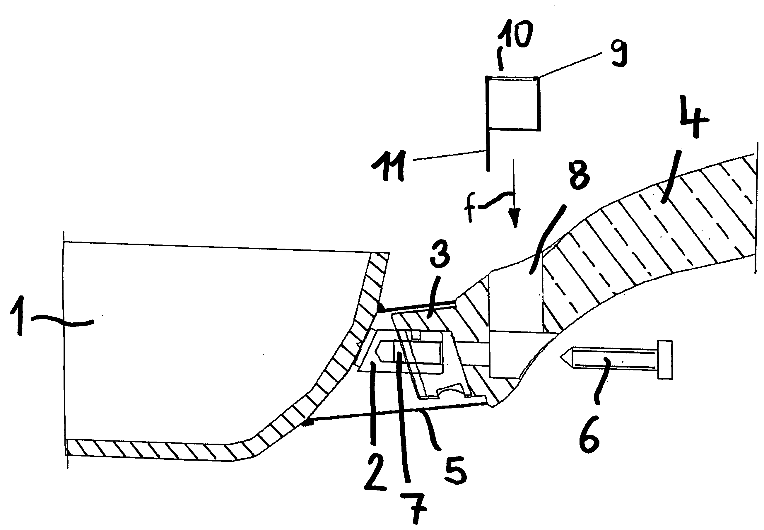
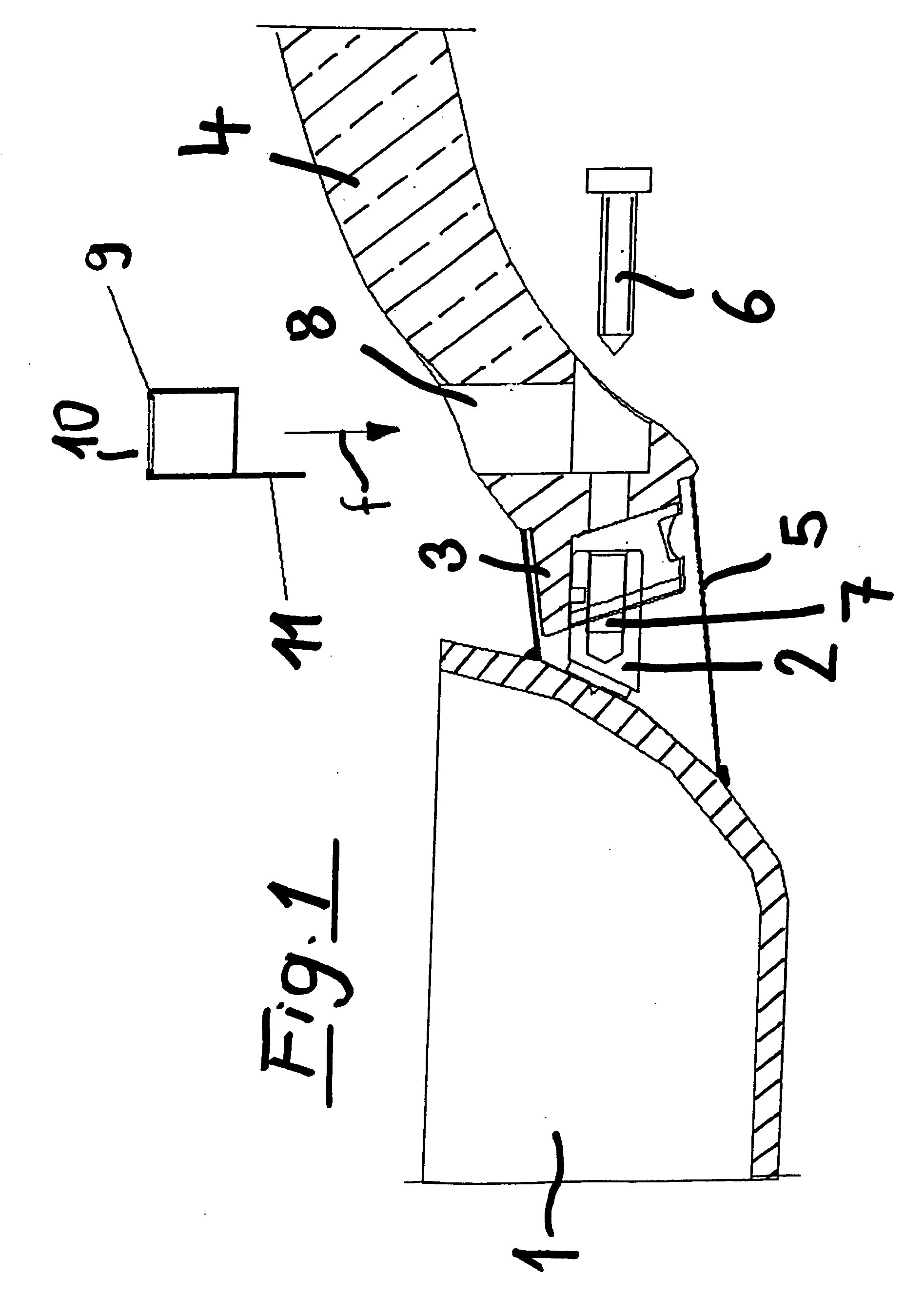
[0017]As is shown in FIG. 1, the food cooking container, for example a pan or pot 1, has a projecting stem element 2 receiving an end seat or recess 3 of a handle 4. Said end portion 3 will be encompassed by a tubular body 5 integral with the body of the pan 1.

[0018]The handle 4 is locked in any known manners, by a clamping screw 6 threaded in a threaded seat 7 of the projecting portion or lug 2.

[0019]More specifically, the handle comprises an upward open seat 8, in which, as indicated by the arrow (f), an envelope 9 advantageously made of a metal material can be engaged, said envelope having a cup-shape including a top opening 10 and a bottom extension 11.

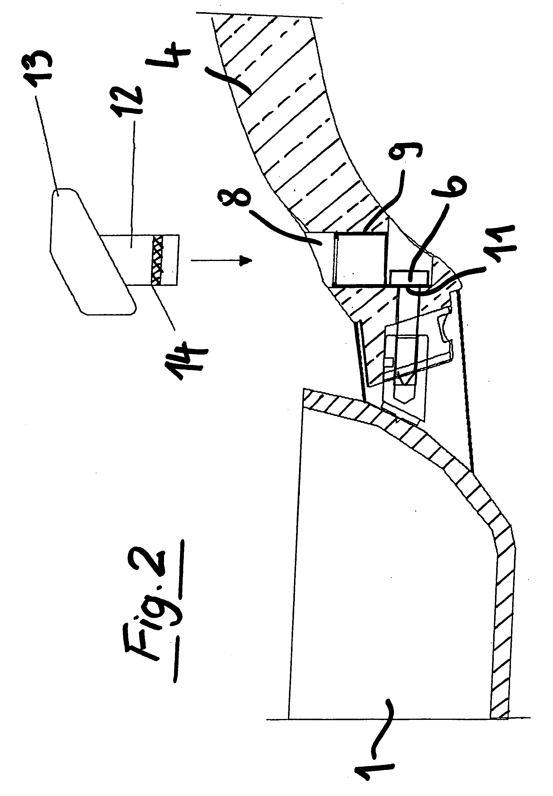
[0020]FIG. 2 shows the metal envelope 9 engaged in the seat 8 of the handle 4, the extension 11 of the envelope being traversed by the clamping screw 6 which also operates as a heat transmission means, for transmitting the heat released by the body of the pan 1.

[0021]Above said handle 4 and under said seat 8, is provided a stem el...


PUM


Abstract

A food cooking container, including a thermal indicator, has a container handle with a seat for engaging an envelope which is thermally conductively coupled to the cooking container body, the envelope having an opening provided for receiving a stem element of a temperature measuring and indicating device, the stem having a region including a plurality of detecting sensors, contacting the envelope walls.

Description

BACKGROUND OF THE INVENTION[0001]The invention relates to a food cooking container.[0002]As it is known, conventional pots and pans for cooking foods usually comprise temperature signaling devices which are built-in, for example, in the container handles and are designed to provide an information related to the achieved cooking temperature or a safety temperature related to the handling of the pots and pans at the end of the cooking operation.[0003]Prior cooking container temperature signaling means usually comprise thermochromatic or liquid crystal die coatings, which, depending on the temperature of the cooking container, change their colors.[0004]Temperature indicators including electronic circuits power supplied by batteries and used for signaling the achieved temperature of the cooking vessel by digital signals, light signals or sounds are also known.[0005]Prior food cooking container temperature signaling systems, however, have the drawback that, as they comprise thermochromat...

Claims


Application Information

Patent Timeline
Patent Type & Authority Applications(United States)
IPC IPC(8): A47J36/00
CPCA47J45/068A47J36/02A47J45/062A47J2202/00
Inventor FERRON, JACOPO
Owner BALLARINI PAOLO E FILI SPA
Why Eureka
Try Eureka