
Adjustable art display

a technology of art display and bracket, which is applied in the direction of reading desks, pulpits, building scaffolds, etc., can solve the problems of not providing a means or suggesting and neither does it disclose or suggest a means for adjusting the distance between the picture and the wall

Inactive Publication Date: 2008-01-31
GEORGE RADOVICH
View PDF24 Cites 23 Cited by
  • Summary
  • Abstract
  • Description
  • Claims
  • Application Information

AI Technical Summary

Benefits of technology

[0009]The other side of the picture plate is placed flat against two picture backing bars. The backing bars have apertures which are placed to align with the apertures on the picture plate to receive fasteners, such a nuts and bolts, and the like, well-known in the art. The two picture backing bars support the artwork and provide a platform to mount the entire assembly to the artwork. Spacing pads, preferably made from felt or other soft material, may be adhesively applied to each backing bar and the front side of the picture plate so as to cushion and protect the picture from the rigid picture plate and backing bars.
[0010]A pivot member is included to provide the ability to adjust the orientation of the artwork relative to the wall. The pivot member has first and second arms with the first arm received by the extension sleeve of the picture plate. The second arm is removably connected to one or more extension rods. The pivot joint permits the user to adjust the displayed artwork. In one preferred embodiment, the pivot member may advantageously be a ball joint which provides 360 degree movement.

Problems solved by technology

However, none of these patents disclose or suggest a means for adjusting the distance between the picture and the wall in a depth dimension, nor do they provide for tilting the plane of the picture with respect to the plane of the wall.

Method used


Image

  • Adjustable art display
  • Adjustable art display
  • Adjustable art display

Examples


Embodiment Construction

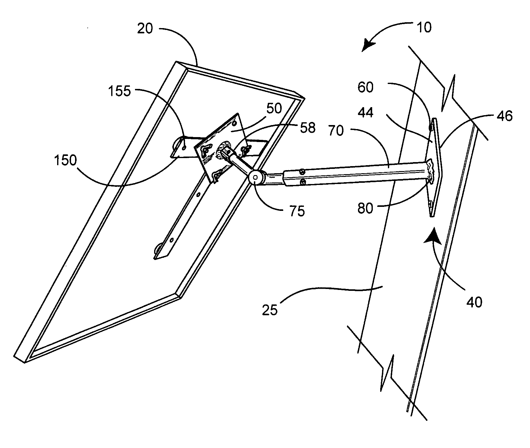
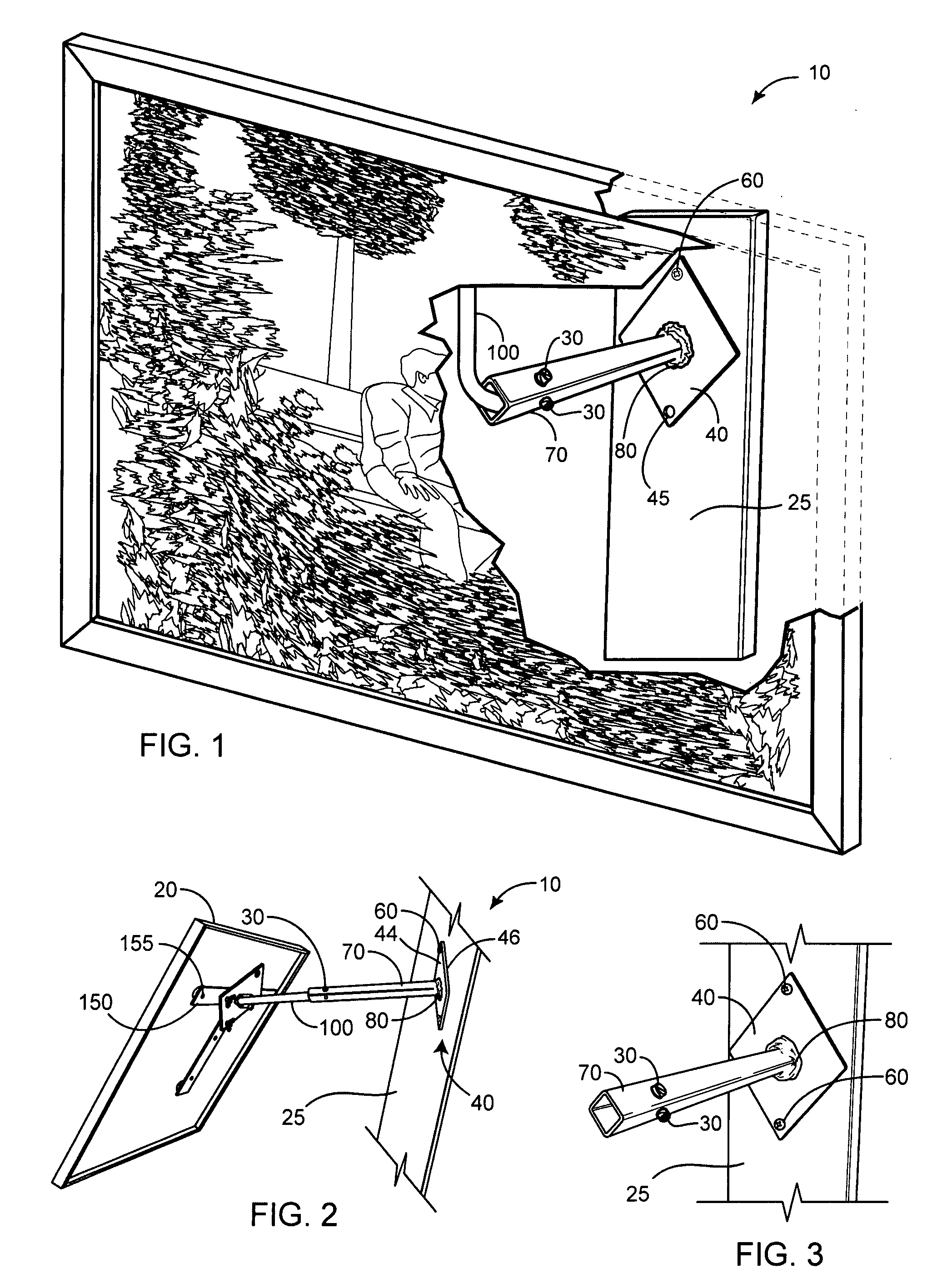
[0027]FIGS. 1 and 2 illustrate an adjustable artwork display 10 for suspending an item or artwork such as a picture 20, projecting outward from a wall surface 25. While the wall surface 25 is illustrated herein, it should be understood that the picture 20 may also be fixed to a door, a post, or any other vertical or horizontal surface as desired. Further, while the framed picture 20 is illustrated in FIGS. 1 and 2, other items (not shown) could easily be mounted to the wall surface 25, such as display cases, paintings, sculptures, craft projects, or any other object suitable for display. Moreover, one of the embodiments of the present invention provides for displaying the artwork from the corner intersection of two walls.

[0028]The adjustable artwork display 10 comprises a rigid, planar base 40 having at least a front side 44, a back side 46, and at least one mounting aperture 45 therethrough. The base 40 is preferably formed from a stock sheet metal material, but may also be a rigid...


PUM


Abstract

An adjustable artwork display for suspending a displayed item, such as a picture, away from a wall surface is disclosed. The mounting bracket comprises a rigid, planar base that includes a rigid extension sleeve projecting away therefrom. At least one rigid extension rod is slidably and rotationally receivable within the extension sleeve and fixed therein. A front side of a picture plate includes at least one hook means adapted to support the picture. A rear side of the picture plate includes an extension rod attachment means that may slidably and rotationally receive the at least one extension rod therein. In use, the base is fixed to the wall surface with a mechanical fastener. With at least one extension rod fixed in the extension sleeve and also fixed to the picture plate, the picture may be suspended from the hook means of the picture plate away from the wall surface. Each extension rod may be rotated and slid within the extension sleeve and the extension rod attachment means of the picture plate to a desired position and fixed therein. As such, the artwork is substantially rigidly fixed to the wall surface, while projecting away from the wall.

Description

CROSS-REFERENCE TO RELATED APPLICATIONS[0001]This application claims the benefit of U.S. Provisional Patent Application 60 / 820,647 filed on Jul. 28, 2006.STATEMENT REGARDING FEDERALLY SPONSORED RESEARCH AND DEVELOPMENT[0002]Not Applicable.FIELD OF THE INVENTION[0003]This invention relates to support brackets, and more particularly to an adjustable bracket for mounting artwork so that it can be projected from a wall.Discussion of Related Art[0004]When hanging a picture, or other artwork displays on a wall, it is often desirable to adjust the position of the picture with respect to the wall. Many prior art devices are used to adjust the picture horizontally and vertically while hanging on the same plane as the wall. Examples of such devices are found in the following U.S. patents:U.S. Pat. No.InventorIssue Date4,892,284KelrickJan. 9, 19905743507RushingApr. 28, 19985,816,557TepperOct. 6, 19984,641,807PhillipsFeb. 10, 19876,550,739BrindisiApr. 22, 2003[0005]All of these patents are suit...

Claims


Application Information

Patent Timeline
IPC IPC(8): A47G1/24
CPCA47G1/24F16M11/04F16M11/12F16M2200/068F16M11/2021F16M13/02F16M11/14
Inventor SCARCELLO, STEPHEN JOSEPH
Owner GEORGE RADOVICH
Features
  • Generate Ideas
  • Intellectual Property
  • Life Sciences
  • Materials
  • Tech Scout
  • Unparalleled Data Quality
  • Higher Quality Content
  • 60% Fewer Hallucinations
Learn More