
Dispensing Assembly for Two Components , Including a Syringe or Dispensing Cartidge and a Mixer

a technology of dispensing assembly and two components, applied in the directions of liquid transferring device, transportation and packaging, packaging, etc., can solve the problems of not being mixed at the correct ratio, creating vacuum,

Inactive Publication Date: 2008-02-07
MEDMIX SYST
View PDF9 Cites 42 Cited by
  • Summary
  • Abstract
  • Description
  • Claims
  • Application Information

AI Technical Summary

Benefits of technology

[0009] None of the prior art references addresses the leveling problem during mixer replacement, and therefore, on the background of this prior art, it is the object of the present invention to provide an assembly for dispensing two components that allows replacing the mixer without affecting the equal filling level of the two components. This is accomplished by the assembly according to claim 1.

Problems solved by technology

Another problem in the removal of mixers designed according to the prior art is the creation of a vacuum.
However, the separation between the components in the cartridge outlet and those in the mixer inlet is not precisely defined and differences in viscosity may have a significant influence.
In this situation, when a new mixer is attached, the two components are not at the same filling level during the dispensing operation and will therefore not be mixed at the correct ratio in the initial phase.
Since the dispensed volumes are small and in addition the media harden quickly after mixing, the resulting requirement is a correct ratio from the beginning as it is problematic to perform a leveling operation after each mixer replacement, i.e. to dispense the mixture until the ratio is correct.

Method used


Image

  • Dispensing Assembly for Two Components , Including a Syringe or Dispensing Cartidge and a Mixer
  • Dispensing Assembly for Two Components , Including a Syringe or Dispensing Cartidge and a Mixer
  • Dispensing Assembly for Two Components , Including a Syringe or Dispensing Cartidge and a Mixer

Examples


Embodiment Construction

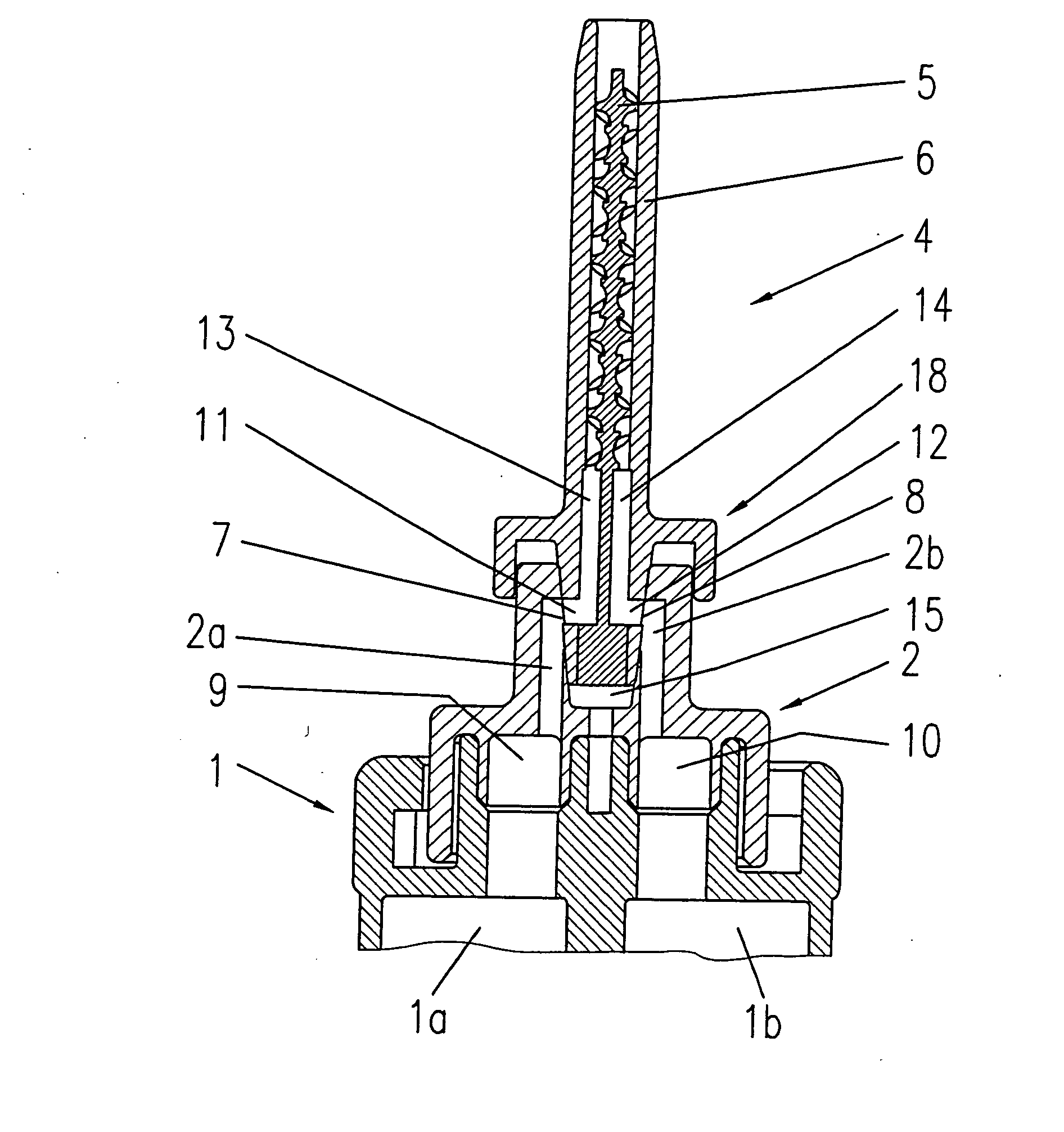
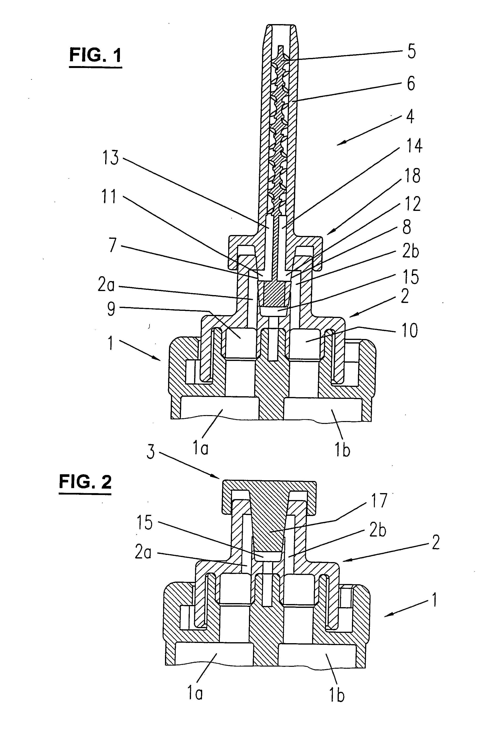
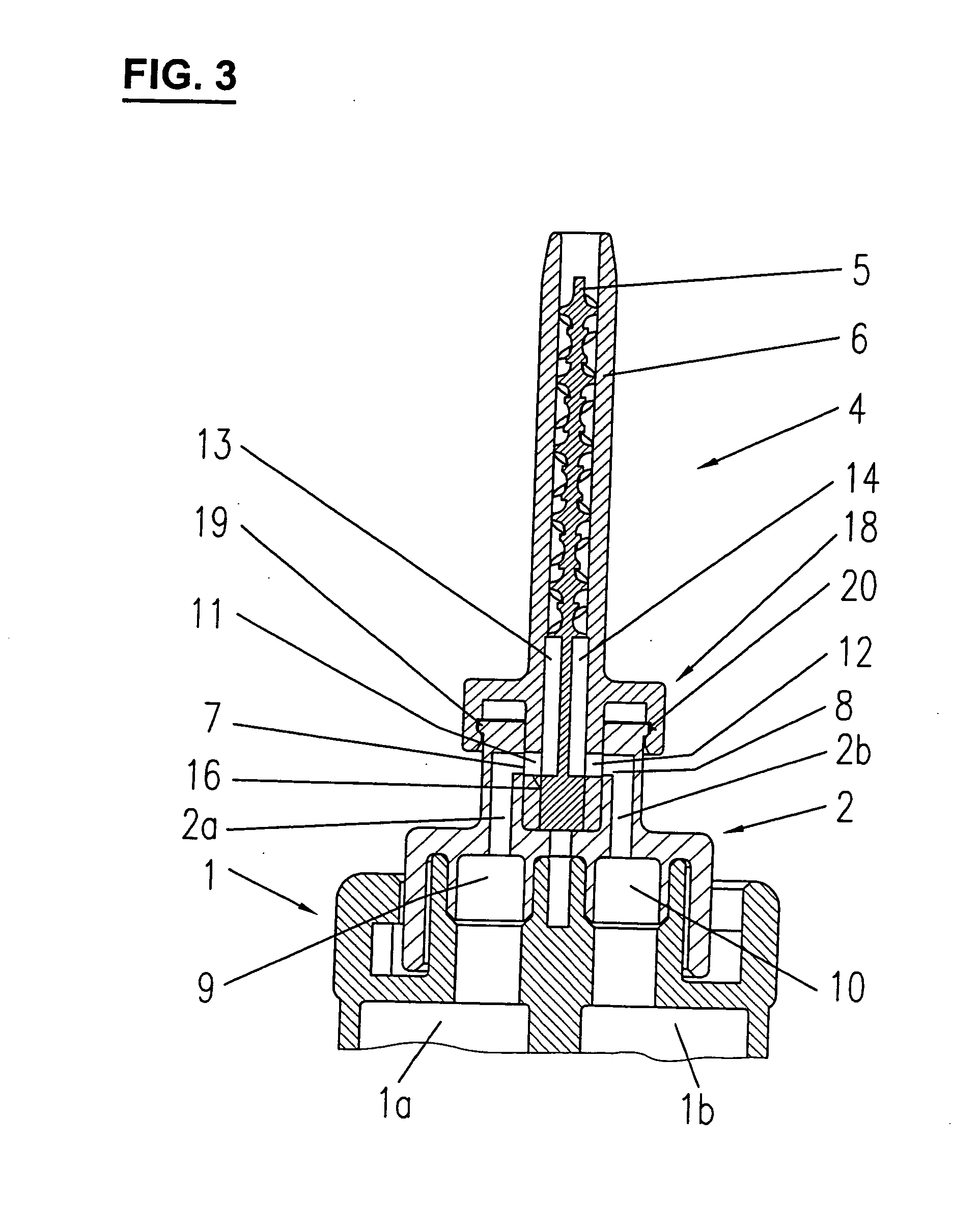
[0020]FIG. 1 illustrates the outlet side of cartridge 1 with the two containers 1a and 1b, an adapter 2 and a mixer 4, and FIG. 2 a closing cap 3. The two outlets 9 and 10 of the cartridge lead into inwardly directed transfer channels 2a and 2b of the adapter and outlets 7 and 8 of the transfer channels into mixer inlets 11 and 12. In contrast to conventional mixers, mixer inlets 11 and 12 are followed by two separating chambers 13 and 14 in order to definitely exclude any cross contamination at the cartridge / mixer interface and thus any hardening during mixer replacement. At the end of the separating chambers, mixing element 5 is arranged which is enclosed in mixer housing 6.

[0021] It is not inventively essential here how the adapter is fastened to the cartridge. In the present case, it is a snap-on arrangement. If conventional cartridges with bayonet sockets are used, it is also possible to provide corresponding bayonet members on the adapter for fastening it to the mixer. Howeve...


PUM


Abstract

The invention relates to a system for dispensing two components, including a syringe or cartridge and a mixer. The system is characterized in that the edges of the mixer inlet openings on the cartridge end and the transfer channel outlets linked with the cartridge outlets are disposed and configured to allow a vacuum-free replacement of the mixer. The planes of the openings on the adapter outlets or on the cartridge outlets or the planes of the openings of the mixer inlets form an angle, especially an angle of 90°, with the longitudinal axes of the outlets or inlets. The inventive systems allows removal of the mixers without producing a vacuum, thereby preserving the filling level of the two components and allowing a correct mixing ratio from the outset once the new mixer is placed on the syringe or cartridge.

Description

CROSS-REFERENCE TO RELATED APPLICATIONS [0001] This application is the National Phase of PCT / CH2005 / 000369, filed Jul. 1, 2005, and published as WO 2006 / 005205, which claims priority from Switzerland Application No. 1168 / 04, filed Jul. 8, 2004, the contents of these applications are incorporated herein by reference.FIELD OF THE INVENTION [0002] The present invention relates to a dispensing assembly for two components including a syringe or dispensing cartridge and a mixer, such assemblies being intended in particular for surgical applications. [0003] A large number of assemblies for dispensing two component materials are on the market in which adhesives or other materials are dispensed from double syringes, double cartridges, or similar dispensing appliances and mixed by means of a static mixer. Frequently, the materials are not dispensed until the cartridges are empty but only partly so that the components in the mixer will harden. [0004] Thus, to continue working, a mixer replacem...

Claims


Application Information

Patent Timeline
IPC IPC(8): B05C17/005B67D5/52B67D7/70
CPCB01F5/0602B01F13/002B01F2215/0039B05C17/00553B05C17/00516B05C17/0052B05C17/00509B01F25/42B01F33/5011B01F2101/2305
Inventor KELLER, WILHELM A.
Owner MEDMIX SYST
Learn More