
Projection-type vehicle headlamp

a technology of vehicle headlamps and projection beams, applied in point-like light sources, transportation and packaging, lighting and heating devices, etc., can solve problems such as glare and harmful light generation

Inactive Publication Date: 2008-03-20
KOITO MFG CO LTD
View PDF6 Cites 4 Cited by
  • Summary
  • Abstract
  • Description
  • Claims
  • Application Information

AI Technical Summary

Benefits of technology

[0008] One or more embodiments of the invention prevent harmful light from being generated by a cover extending in a forward direction.

Problems solved by technology

In such a case, a part of the light is likely to be irradiated directly toward the cover 7 and reflected, whereby harmful light, such as glare, is generated.

Method used


Image

  • Projection-type vehicle headlamp
  • Projection-type vehicle headlamp
  • Projection-type vehicle headlamp

Examples


Embodiment Construction

[0017] Hereinafter, exemplary embodiments of the invention will be explained with reference to the drawings, the following exemplary embodiments do not limit the scope of the invention.

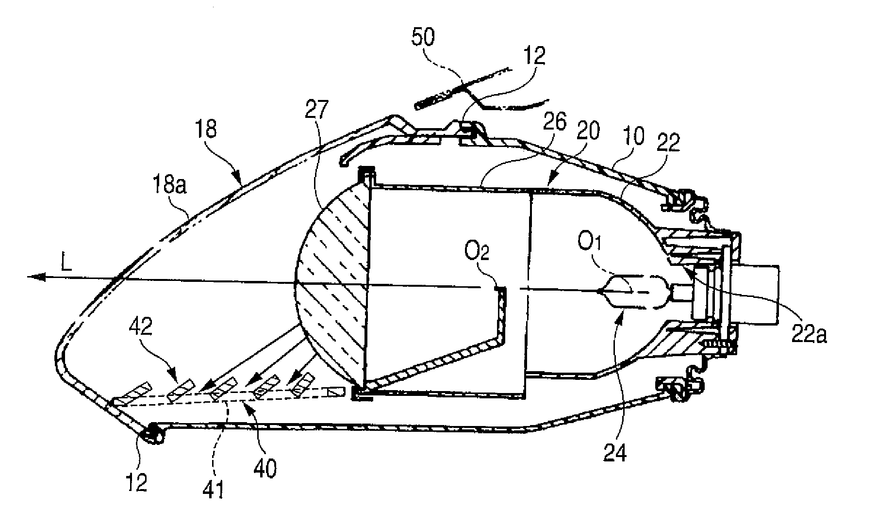
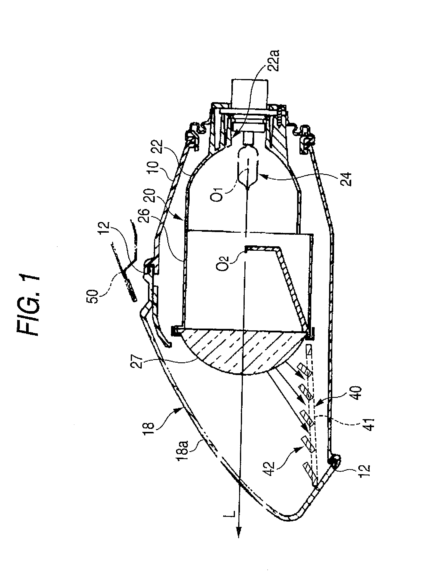
[0018] A lamp body 10 shown in FIG. 1 has a shape of a rectangular container when seen from the front, and an opening having a shape of an obliquely upward rectangle is formed on a front side of the lamp body. A peripheral edge of the opening is formed with a sealing groove 12. A leg portion of a front cover 18 is engaged with the sealing groove 12 with a sealing agent disposed therebetween, whereby the front cover 18 and the lamp body 10 are assembled together. A front surface 18a of the front cover 18 is greatly inclined with respect to an upward direction so that a vertical section thereof has a streamline shape conforming to a shape of a body (a bonnet) 50 when the front cover 18 is assembled to the lamp body 10. A light projection unit 20 and a clearance lamp (not shown) are disposed adjacent to...


PUM


Abstract

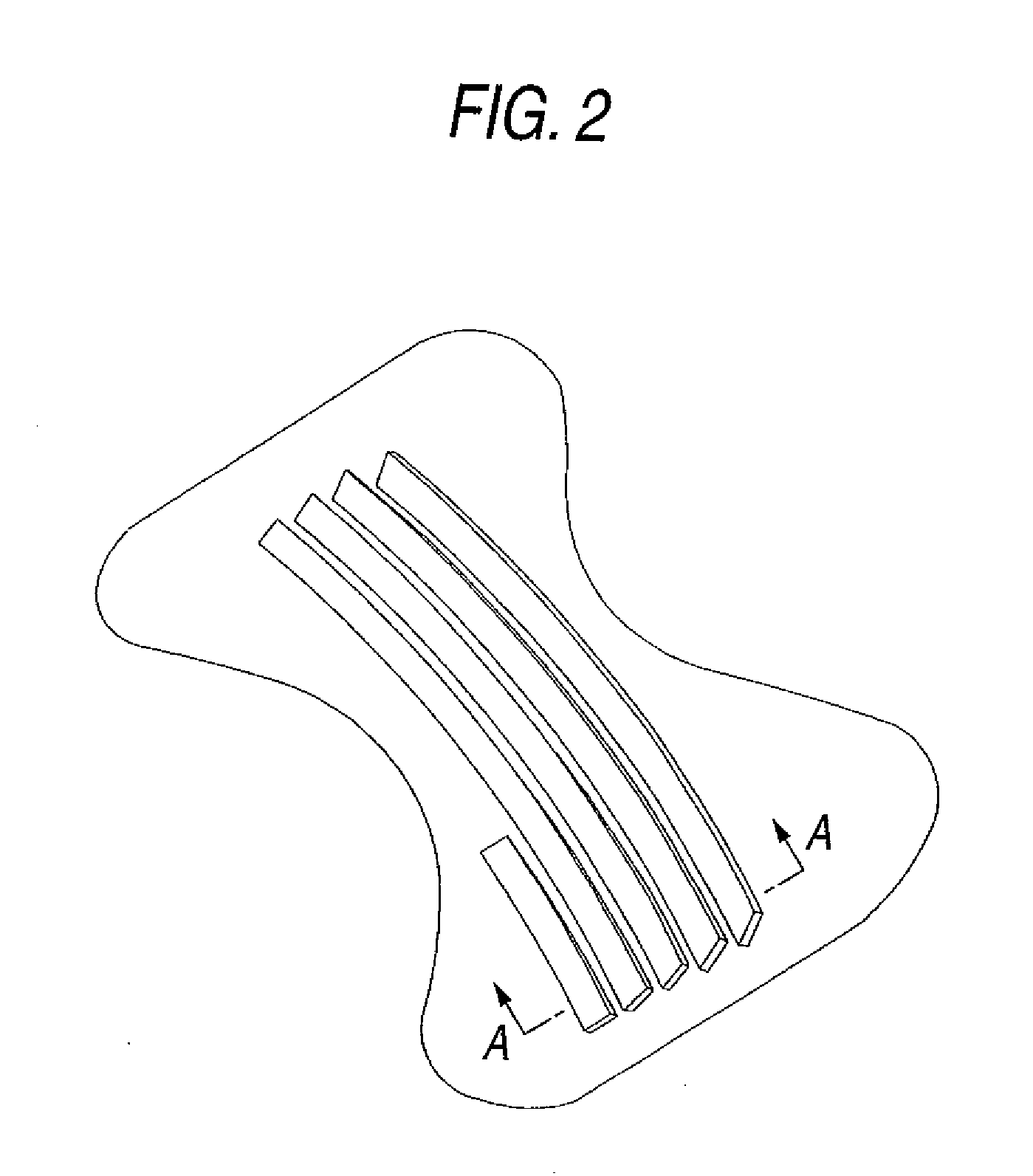
A projection-type vehicle headlamp includes a lamp body, a front cover forming a lamp housing together with the lamp body, a light projection unit accommodated inside the lamp body, and a cover extending in a forward direction from the light projection unit. A louver is formed on a portion of the cover where light from the light projection unit is irradiated so as to allow irradiated light to pass through the louver.

Description

CROSS-REFERENCE TO RELATED APPLICATIONS [0001] The present invention claims priority from Japanese Patent Application No. 2006-252741 filed on Sep. 19, 2006, the entire content of which is incorporated herein by reference. BACKGROUND OF INVENTION [0002] 1. Field of the Invention [0003] The present invention relates to a projection-type vehicle headlamp including a light projection unit in which light from a light source is reflected by a ellipsoidal reflector and then is forwardly projected and distributed via a projection lens. [0004] 2. Background Art [0005] As shown in FIG. 6, a projection-type vehicle headlamp includes a lamp body 1, a front cover 2 which forms a lamp housing together with the lamp body 1, and a light projection unit 3 accommodated inside the lamp housing. The light projection unit 3 includes a light source 3a, a reflector 3b having a substantially ellipsoidal shape, and a projection lens 3c, which are assembled together. Light from a light source is reflected b...

Claims


Application Information

Patent Timeline
Patent Type & Authority Applications(United States)
IPC IPC(8): B60Q1/04F21Y101/00
CPCF21S48/10F21V11/02F21S48/1258F21S41/255F21S41/43
Inventor OHTAKI, SUMITOSHIMAKURA, KOHJIKONAGAI, NORIYUKIMATSUMOTO, AKINORIMORITANI, TOMOYUKI
Owner KOITO MFG CO LTD
Learn More