
Optical film

Active Publication Date: 2008-03-27
ETERNAL MATERIALS CO LTD
View PDF9 Cites 8 Cited by
  • Summary
  • Abstract
  • Description
  • Claims
  • Application Information

AI Technical Summary

Benefits of technology

[0005]Accordingly, an object of the present invention is to provide an optical film which can address the aforementioned problems as well as provide various advantages. The optical film of the present invention comprises a top surface which includes a micro-hemisphere layer, and a bottom surface which is an unsmooth surface. The light is diffused and uniformed by the unsmooth diffusion layer and then condensed by the micro-hemisphere layer. Therefore, with the optical film of the present invention, a better light uniformity and light condensation can be achieved.
[0006]Another object of the present invention is to provide an optical film for an LCD which is thin, lightweight, compact, and cost-effective.

Problems solved by technology

However, this has a tendency of accumulating an excess of heat generated by the lamps in the panel, resulting in a short lifetime and a poor performance of constituting elements of the panel.
Furthermore, a large amount of power consumption resulted from the increase in the number of lamps is not suitable for battery-powered portable applications.
However, this results in cost incense and a complex backlight module.

Method used


Image

  • Optical film
  • Optical film
  • Optical film

Examples


Embodiment Construction

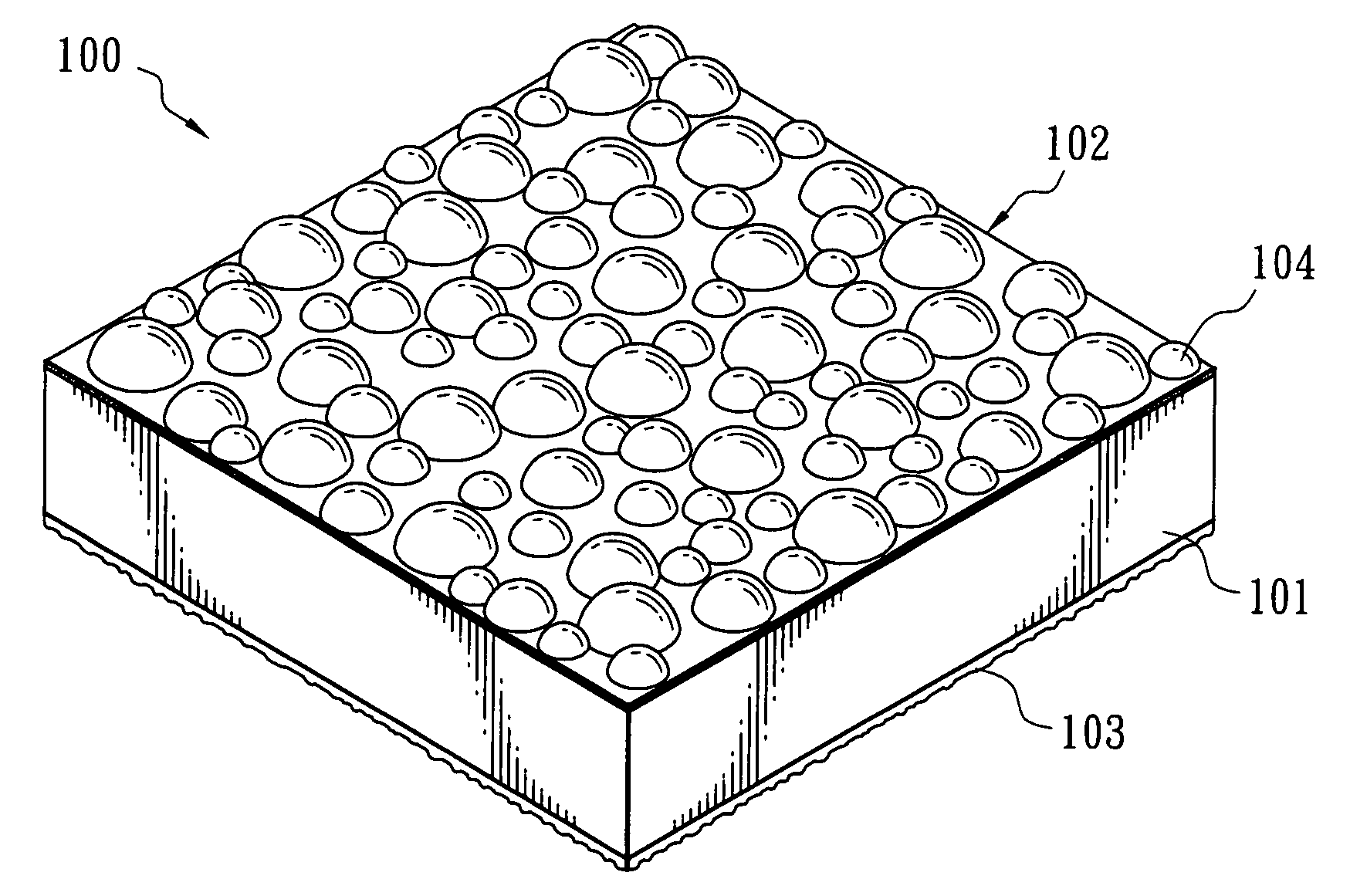
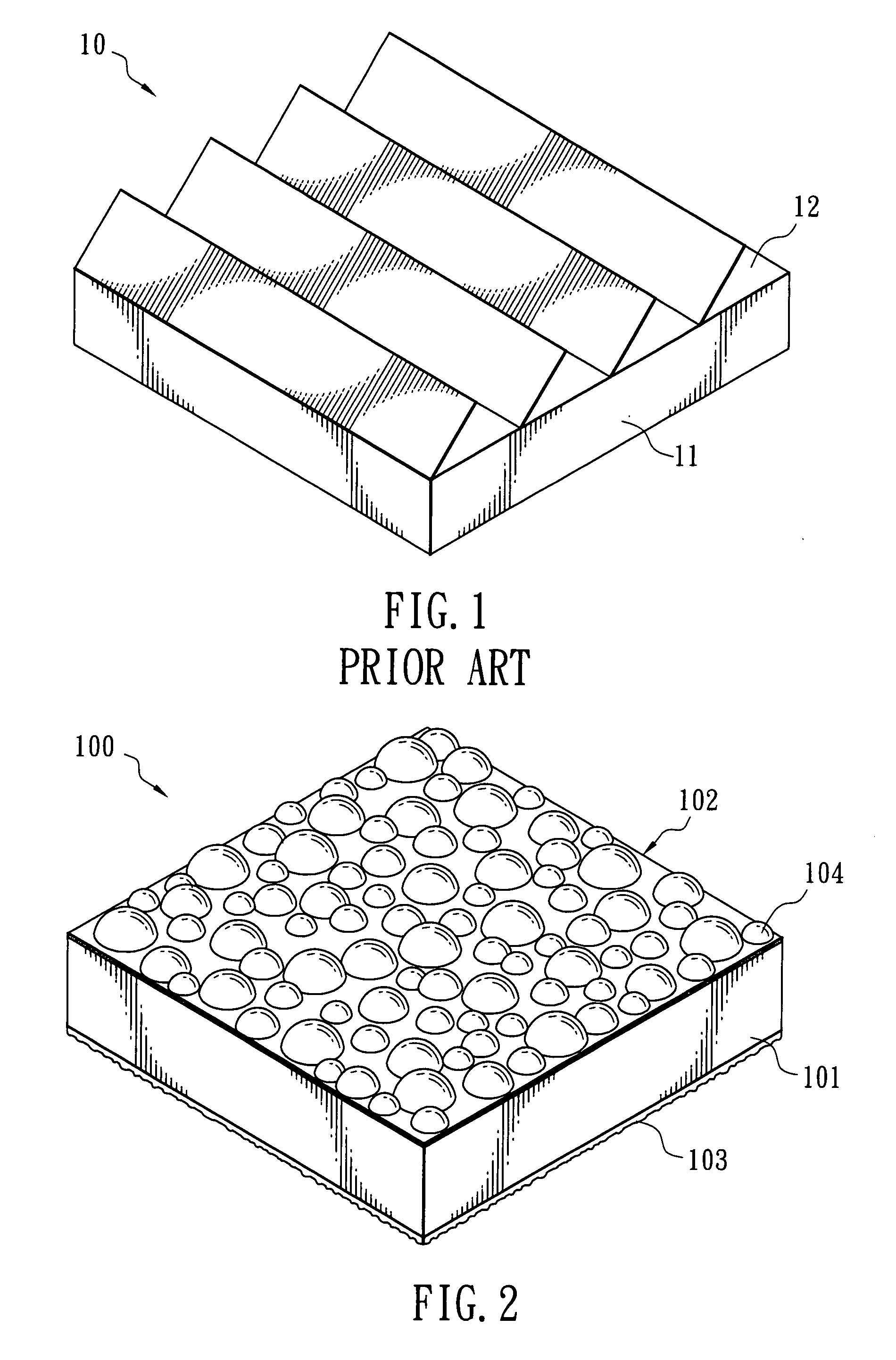
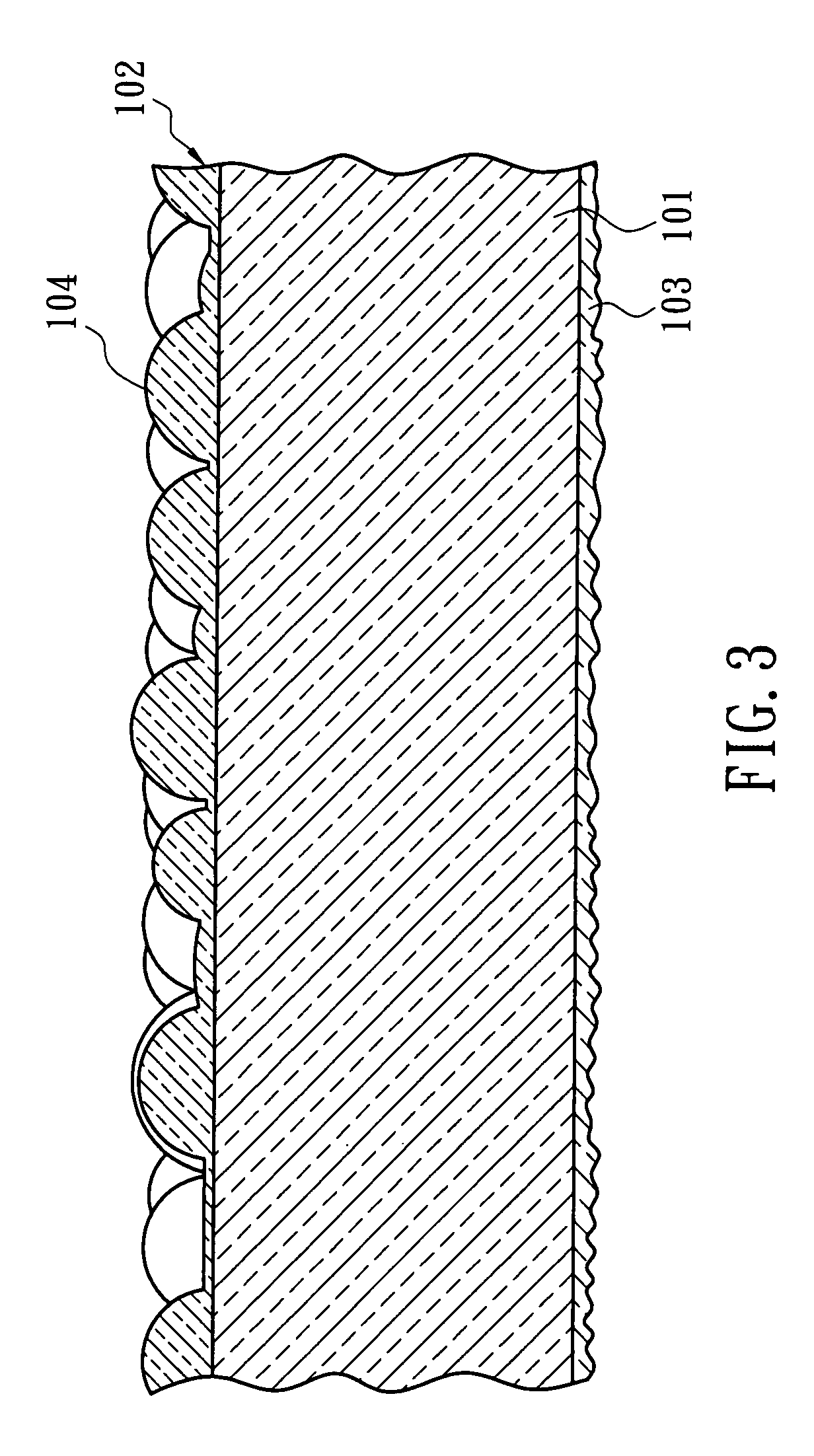
[0013]Referring to FIG. 2, an optical film 100 in accordance with the present invention is shown. The optical film 100 includes a transparent substrate 101, a micro-hemisphere layer 102 formed on a top surface of the transparent substrate 101, and a unsmooth diffusion layer 103 formed on a bottom surface opposite to the top surface of the transparent substrate 101.

[0014]The transparent substrate 101 used in the optical film 100 in accordance with the present invention may be any substrate known to those skilled in the art, such as glass or plastic. There are no specific restrictions with respect to the aforementioned plastic substrate including, but not limited to a polyester resin, such as polyethylene terephthalate (PET); a polyacrylate resin, such as polymethyl methacrylate (PMMA); a polyolefin resin, such as polyethylene (PE) or polypropylene (PP); a polyimide resin; a polycarbonate resin; a polyurethane resin; cellulose triacetate (TAC); or a mixture thereof. The thickness of t...


PUM


Abstract

An optical film comprises a transparent substrate including a top surface and a bottom surface; a micro-hemisphere layer disposed on the top surface of the transparent substrate and having a plurality of hemispheric projections, and an unsmooth surface diffusion layer disposed on the bottom surface of the transparent substrate. The micro-hemisphere layer condenses a light. The unsmooth diffusion surface diffuses a light.

Description

BACKGROUND OF THE INVENTION[0001]This invention relates to an optical film, and more particularly, to an optical film for a liquid crystal display.DESCRIPTION OF RELATED ART[0002]In order to acquire better viewing angle and color characteristics of a LCD, various attempts have been made. For example, it is known that the brightness of an LCD panel can be enhanced by increasing the number of lamps. However, this has a tendency of accumulating an excess of heat generated by the lamps in the panel, resulting in a short lifetime and a poor performance of constituting elements of the panel. Furthermore, a large amount of power consumption resulted from the increase in the number of lamps is not suitable for battery-powered portable applications. It has been considered the most economical and convenient approach to effectively increase the brightness of an LCD panel so as to make the best of a light source by employing various optical films in backlight modules without conducting any elem...

Claims


Application Information

Patent Timeline
IPC IPC(8): G02B5/02
CPCG02B5/0278G02B5/0221
Inventor CHUANG, SHIH-YI
Owner ETERNAL MATERIALS CO LTD
Features
  • Generate Ideas
  • Intellectual Property
  • Life Sciences
  • Materials
  • Tech Scout
  • Unparalleled Data Quality
  • Higher Quality Content
  • 60% Fewer Hallucinations
Learn More