Light emitting sign and display surface therefor

Inactive Publication Date: 2007-10-18
INTEMATIX
View PDF7 Cites 188 Cited by
  • Summary
  • Abstract
  • Description
  • Claims
  • Application Information

AI Technical Summary

Benefits of technology

[0012] According to the present embodiments, a light emitting sign comprises: a light emitting display surface including at least one phosphor; and at least one radiation source operable to generate and radiate excitation energy of a selected wavelength range, the source being configured to irradiate the display surface with excitation energy such that the phosphor emits radiation of a selected color and wherein the display surface is selectable to give a different selected color of emitted light from the same radi

Problems solved by technology

Often, the light box is custom fabricated from sheet metal as a rectangular box or as a box in the shape of a required letter/character/symbol (channel letter) and such construction in conjunction with the white light source can account for a significant proportion of the total cost of the sign.
A disadvantage of such signs is that a color filter has to be fabricated for every color required which increases the cost.
In addition, while such signs give a good performance at night they give poor color performance in daylight conditions due to their mode of operation which relies on the transmission rather than reflection of light and such signs can appear “washed out”.
Moreover

Method used


Image

  • Light emitting sign and display surface therefor
  • Light emitting sign and display surface therefor
  • Light emitting sign and display surface therefor

Examples


Example

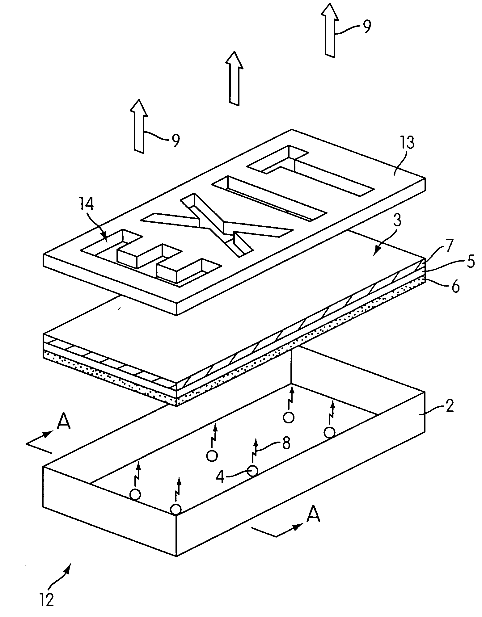
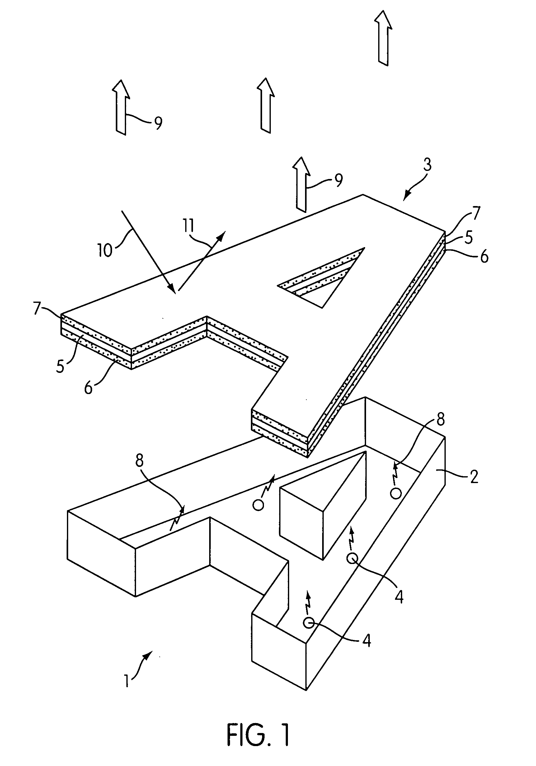
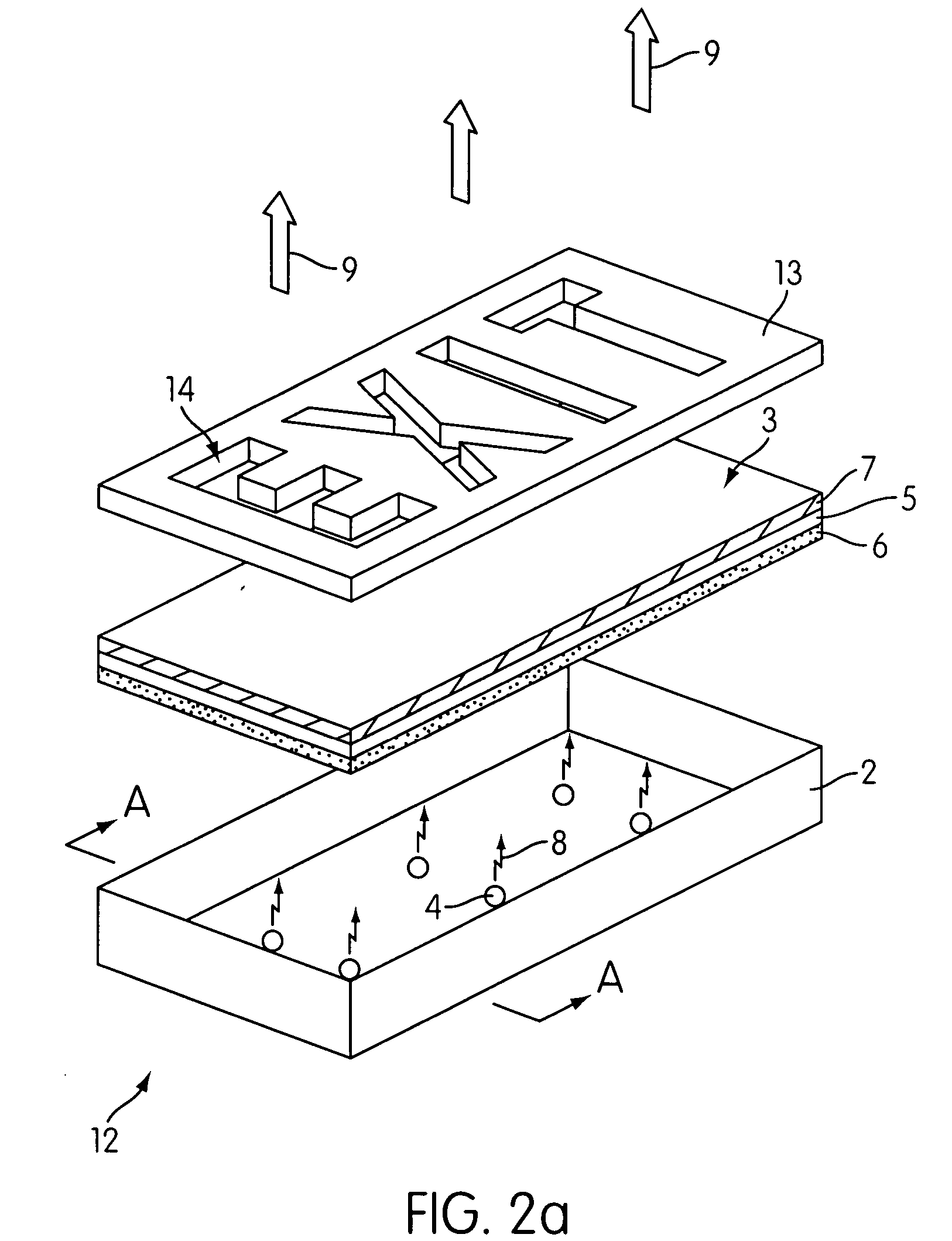
[0040] Referring to FIG. 1 there is shown an exploded perspective view of a backlit light emitting sign 1 in accordance with the invention. In the example illustrated the sign 1 is intended to generate a letter “A” and comprises a light box 2 which is configured in the shape of the letter “A”. The light box can be fabricated from sheet metal, molded from a plastics material or constructed from any other suitable material. The inner surface of the light box preferably includes a light reflective surface to reflect light towards a light emitting display surface 3 of the sign. A number of light emitting diodes (LEDs) 4 are provided within the light box 2 and are preferably blue LEDs which emit blue light in a wavelength range 410 to 470 nm.

[0041] The light emitting display surface 3 is substantially planar in form and is configured in shape to define the letter “A”. The display surface 3 comprises a transparent / translucent substrate 5 such as for example a polycarbonate, polythene, ac...


PUM


Abstract

A light emitting sign comprising a light emitting display surface including at least one phosphor, and at least one radiation source configured to irradiate the display surface with excitation energy such that the phosphor emits light of a selected color. The sign further comprises a filter which is substantially transparent to light emitted by the display surface, filtering other colors of light. The display surface may be configured into a shape of a character, a symbol, or a device. Alternatively, a mask having at least one window substantially transparent to the emitted light and/or at least one light blocking region may be provided in which the window and/or light blocking region define a character, a symbol, or a device.

Description

BACKGROUND OF THE INVENTION [0001] 1. Field of the Invention [0002] The invention relates to light emitting signs and light emitting display surfaces for generating fixed images, graphics, photographic images and characters of a desired color of light. In particular the invention concerns light emitting signs which utilize a semiconductor light emitting diode (LED) and a phosphor (photo luminescent) material to generate a desired color of emitted light. Moreover the invention relates to generating colored light over large surface areas. [0003] 2. Description of the Related Art [0004] Light emitting signs / displays, sometimes termed illuminated signs or displays, are used in many applications including: name signs for business premises using fixed graphics and characters, fixed image signs for advertising, emergency signs such as exit signs, traffic signals, road signs for example speed limit, stop, give way (yield) signs, direction indicator signs to name but a few. [0005] A common w...

Claims


Application Information

Patent Timeline
IPC IPC(8): G09F13/22
CPCG09F13/20G09F13/0404G09F13/22
Inventor LI, YI-QUNDONG, YICARUSO, JAMESEDWARDS, CHARLES O.
Owner INTEMATIX
Why Eureka
Try Eureka