Self-activated fire extinguisher

Inactive Publication Date: 2008-04-17
AMERON GLOBAL
View PDF15 Cites 19 Cited by
  • Summary
  • Abstract
  • Description
  • Claims
  • Application Information

AI Technical Summary

Benefits of technology

[0009]The fire extinguisher may comprise two or more tubes extending from a single fitting. Each tube would contain its own valve having its own temperature sensor. The tub

Problems solved by technology

None of the prior art devices provide for easily recharging the

Method used


Image

  • Self-activated fire extinguisher
  • Self-activated fire extinguisher
  • Self-activated fire extinguisher

Examples


Embodiment Construction

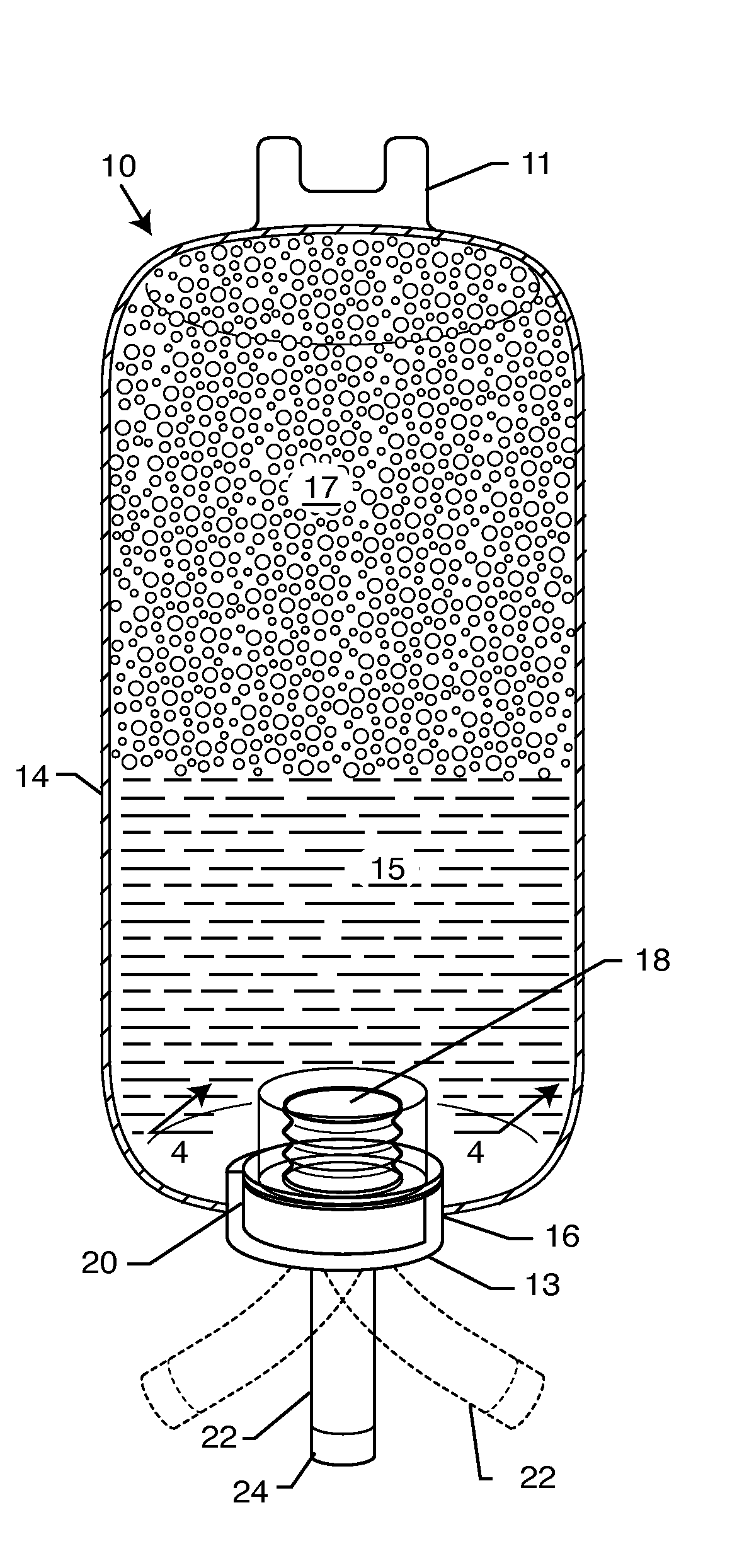
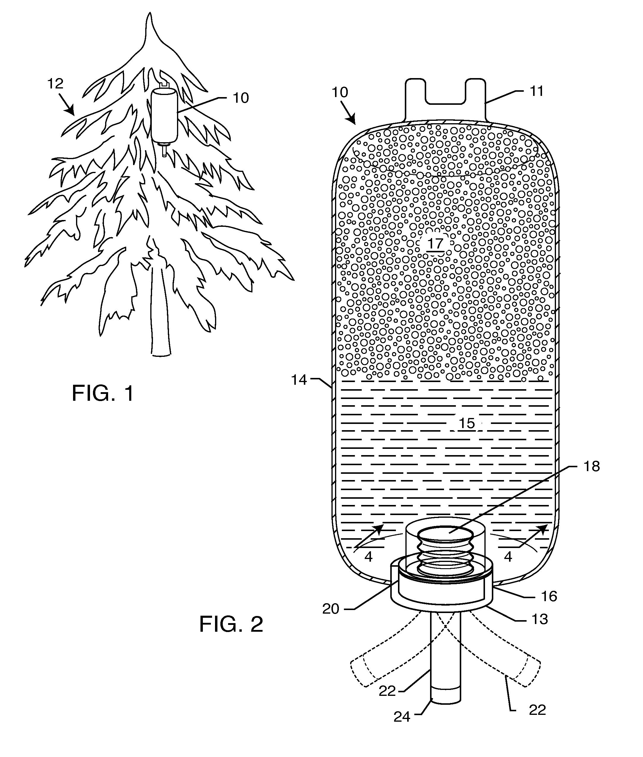
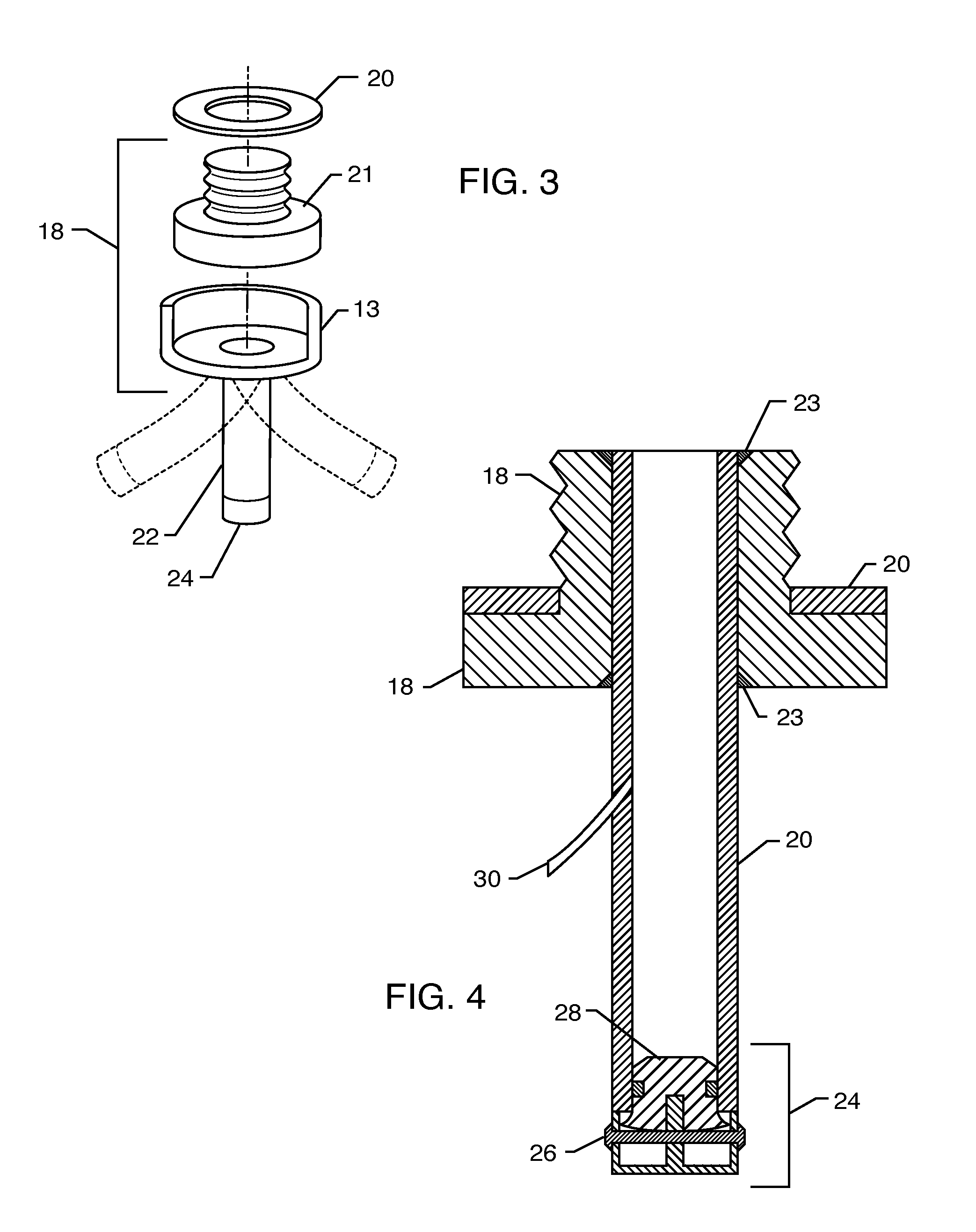
[0017]As shown in the drawings for purposes of illustration, the present invention relates to a self-activated fire extinguisher primarily for use as a Christmas tree ornament or decoration. FIG. 1 depicts the self-activated fire extinguisher 10 in an environmental view on a Christmas tree 12. FIGS. 2-4 illustrate a preferred embodiment of the self-activating fire extinguisher 10.

[0018]The self-activating fire extinguisher 10 consists of a plastic pressure vessel 14 that can be molded or configured in a variety of shapes such as spherical or cylindrical. The pressure vessel 14 may or may not be painted or decorated with an external facade to suit various usage requirements, i.e., as a Christmas decoration. The pressure vessel 14 includes mounting tabs 11 integrally molded onto the surface.

[0019]The pressure vessel 14 is capable of housing a variety of fire suppressant agents such as a liquid, a powder, or combinations of both. Such fire suppressant agents include Purple K Powder or ...


PUM


Abstract

An automatic fire extinguisher that is self-activated in the presence of specified temperature. The fire extinguisher includes a sealed pressure vessel having a fitting and a tube permitting access to the contents of the pressure vessel. A valve in the end of the tube includes a fusible alloy temperature sensor designed to melt or soften in the presence of heat and/or flame. Once the temperature sensor softens or melts, the contents of the pressure vessel are released through the valve thereby extinguishing the fire. A capillary tube is provided to charge the pressure vessel with fire suppressant agent and a pressurized gas.

Description

BACKGROUND OF THE INVENTION[0001]This invention relates generally to fire extinguishers, particularly of the type that are self-activated, i.e., as in the case of a heat sensor or a fire sensor. In addition, the fire extinguisher of the present invention is designed particularly for use as a Christmas tree ornament or other decoration. The fire extinguisher is heat activated and requires no electrical or battery power to function.[0002]Fire extinguishers that automatically discharge in the presence of heat and / or fire are well known in the art. U.S. Pat. No. 3,171,493 to Barr discloses a fire protection device for a Christmas tree, wherein a valve opening is obstructed by one end of a pair of aligned rods held together by fusible metal which melts upon a corresponding rise in temperature. The valve opening is configured to eject a fire extinguishing foam upward so that it reflects off of a concave surface.[0003]U.S. Pat. No. 2,876,845 to Boyce discloses a fire extinguisher for Chris...

Claims


Application Information

Patent Timeline
IPC IPC(8): A62C37/12A62C37/50
CPCA62C37/12A62C13/62
Inventor SITABKHAN, ABDUL
Owner AMERON GLOBAL
Why Eureka
Try Eureka