Lamp structure with adjustable projection angle

a technology of projection angle and lamp structure, which is applied in the direction of lighting and heating apparatus, semiconductor devices for light sources, lighting support devices, etc., can solve the problems of reducing the practicability and the scope of applicability of the lamp structure, increasing the cost of molds and extending the time for developing and manufacturing lamps, and incurring a cost for making molds of different components

Inactive Publication Date: 2008-04-17
LEADER KEY +1
View PDF2 Cites 175 Cited by
  • Summary
  • Abstract
  • Description
  • Claims
  • Application Information

AI Technical Summary

Problems solved by technology

However, the traditional LED lamp structure still has the following drawbacks on its usage.
Since the traditional lamp structure does not come with a rotating rack connected to the lamp housing, the projection angle of the LED module cannot be adjusted or changed to cope with the illumination requirements for different positions or provide light required in an illumination area, and thus greatly reducing the practicability and the scope of applicability of the lamp structure.
Furthermore, it is necessary to produce different molds for different models of lamp structures according to their specifications or powers, and thus further increasing the cost for making molds and extending the time for developing and manufacturing the lamps.
The lamp housing, partition and heat sink must be manufactured separately, not only incurring a cost for making the molds of different components, but also requiring a complicated manufacturing process and increasing the manufacturing and assembling costs significantly.
Further, the traditional LED lamp structure only uses heat pipes for heat dissipation, but the heat pipe has a very limited surface area in contact with the LED lamp, and thus the quantity of dissipated heat is also limited.

Method used


Image

  • Lamp structure with adjustable projection angle
  • Lamp structure with adjustable projection angle
  • Lamp structure with adjustable projection angle

Examples


Embodiment Construction

[0018]The technical characteristics, features and advantages of the present invention will become apparent in the following detailed description of the preferred embodiments with reference to the accompanying drawings. However, the drawings are provided for reference and illustration only and are not intended for limiting the scope of the invention.

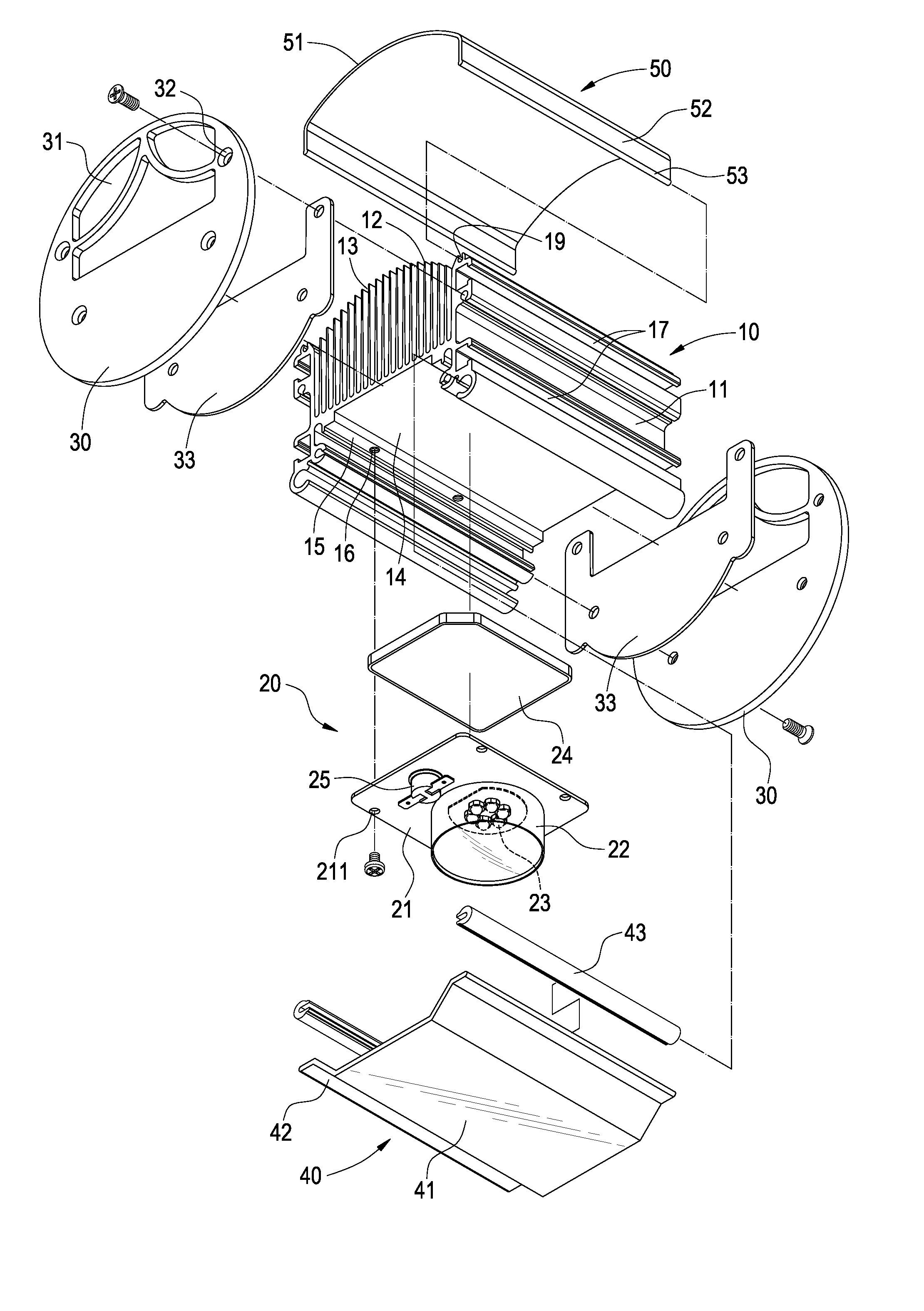
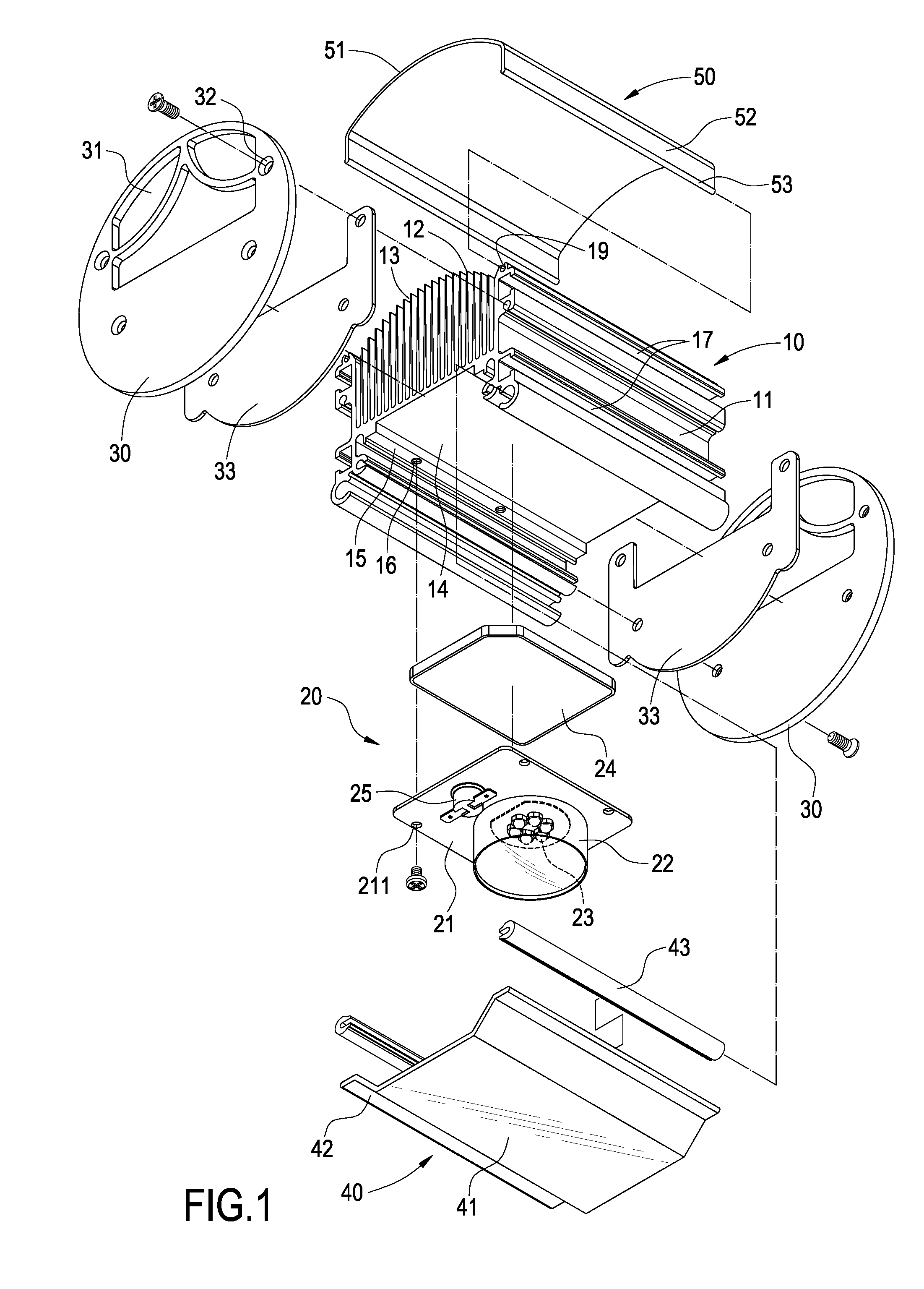
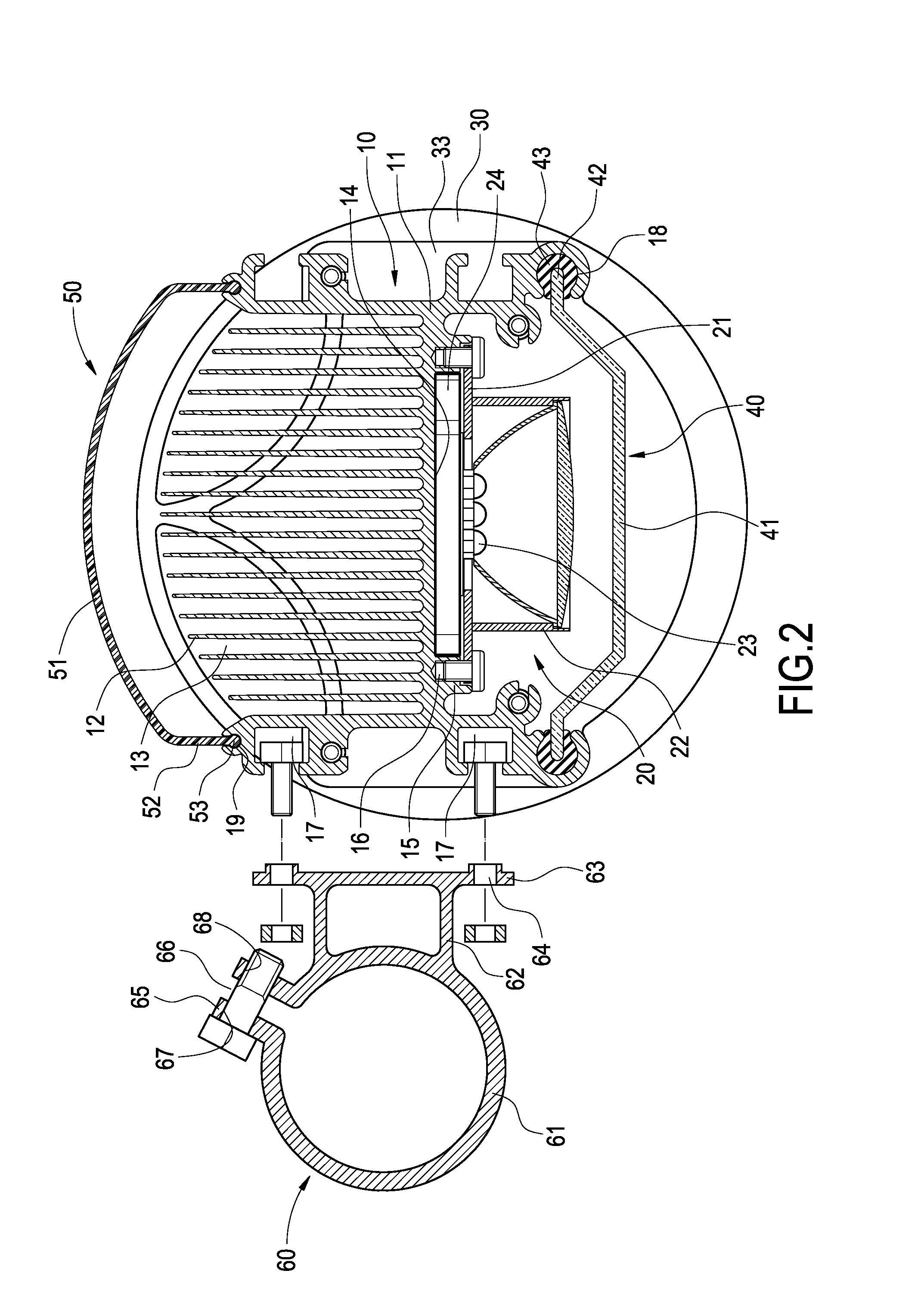
[0019]Referring to FIGS. 1 to 3 for an exploded view of a lamp housing, an LED module, and each lampshade in accordance with the present invention, and a cross-sectional view and a perspective view of a lamp housing and a rotating rack in accordance wit the present invention respectively, the invention provides a lamp structure with adjustable projection angle, comprising an aluminum extrusion lamp housing 10, an LED module 20 and a rotating rack 60.

[0020]The lamp housing 10 is shaped integrally and extruded by an aluminum material, and the lamp housing 10 includes a substantially H-shape base 11, a plurality of heat sinks 12 extended fro...


PUM


Abstract

An LED lamp structure with adjustable projection angle includes an aluminum extrusion lamp housing, an LED module, and a rotating rack. The lamp housing has a base, a plurality of heat sinks extended from the base, and a receiving portion formed on an external side of the base. The LED module includes a fixing base, a lampshade on a side of the fixing base, and a plurality of LED lamps in the lampshade, and the fixing base is coupled in the base of the lamp housing. The rotating rack has a hollow cylindrical body, a fixing board extended from a side of the cylindrical body, and a connecting portion formed on the fixing board and connected to the corresponding receiving portion, so that the projection angle of the LED module can be adjusted according to the illumination requirements for different positions and provide the light required for the illumination area.

Description

BACKGROUND OF THE INVENTION[0001]1. Field of the Invention[0002]The present invention relates to a lamp structure with adjustable projection angle, and more particularly to a lamp structure capable of adjusting a projection angle of an LED module.[0003]2. Description of Prior Art[0004]Since light emitting diodes (LEDs) feature the advantages of high brightness, power saving and long life expectancy, LEDs have been used extensively for illuminations. Several LED lamps are usually arranged and connected to a circuit board to form an LED lamp module and several LED lamp modules are connected in series or in parallel to constitute a lamp structure to achieve an illumination effect that meets the requirements for a large projecting area and a high brightness for outdoor illuminations, and serve for indoor or outdoor illuminations.[0005]A traditional lamp structure includes a lamp housing, a light-transmitting hood, a partition and an LED module, wherein the lamp housing includes a ventil...

Claims


Application Information

Patent Timeline
Patent Type & Authority Applications(United States)
IPC IPC(8): F21V29/00
CPCF21S2/005F21V15/013F21V21/116F21V21/30F21V25/10F21V29/004F21V29/83F21Y2101/02F21V31/005F21V3/02F21V15/015F21V29/75F21V29/763F21W2131/10F21Y2115/10F21V17/104F21V17/12
Inventor WANG, CHIN-WEN
Owner LEADER KEY
Why Eureka
Try Eureka