Flexible delivery system

Inactive Publication Date: 2008-05-15
MED INST INC
View PDF75 Cites 36 Cited by
  • Summary
  • Abstract
  • Description
  • Claims
  • Application Information

AI Technical Summary

Benefits of technology

[0017]According to another aspect of the invention, a pusher may be provided that comprises a first material along a first portion thereof, and a second material along a second portion thereof where the first material is more flexib

Problems solved by technology

While it may be practical to use highly flexible materials for some applications, such as the introducer sheath, their use may be impractical for other applications, such as the pusher.
In general, soft and flexible materials may not possess sufficient structural integrity or strength for pusher applications.
To this end, prior art pushers have been provided that are generally rigid and consequently have poor trackability.
There are many disadvantages of using a rigid pus

Method used


Image

  • Flexible delivery system
  • Flexible delivery system
  • Flexible delivery system

Examples


Example

[0042]Throughout the specification, the terms “distal” and “distally” shall denote a position, direction, or orientation that is generally toward the patient. Accordingly, the terms “proximal” and “proximally” shall denote a position, direction, or orientation that is generally away from the patient.

[0043]Throughout the specification, unless the context requires otherwise, the words “comprise” and “include” and variations such as “comprising” and “including” will be understood to imply the inclusion of an item or group of items, but not the exclusion of any other item or group of items.

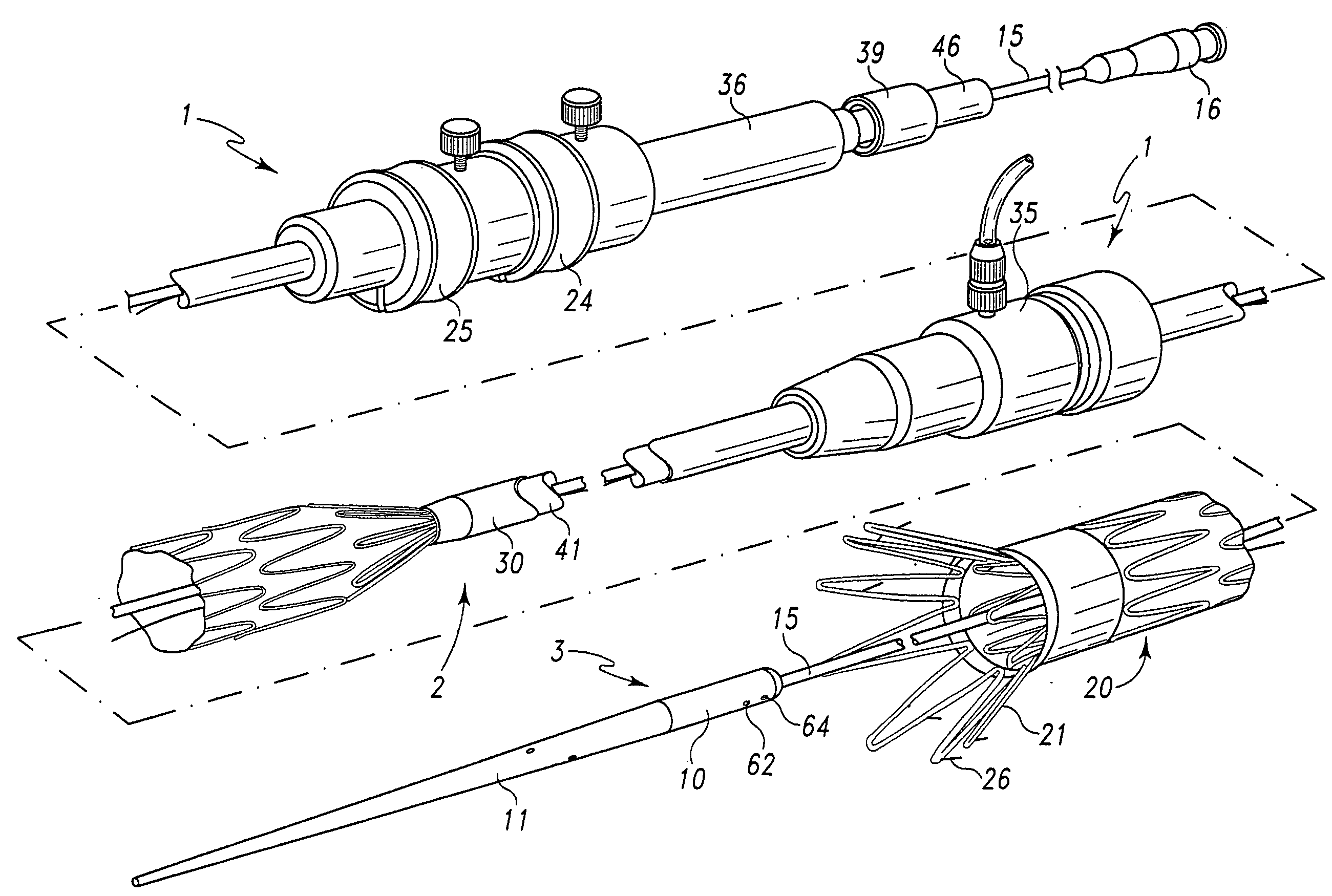
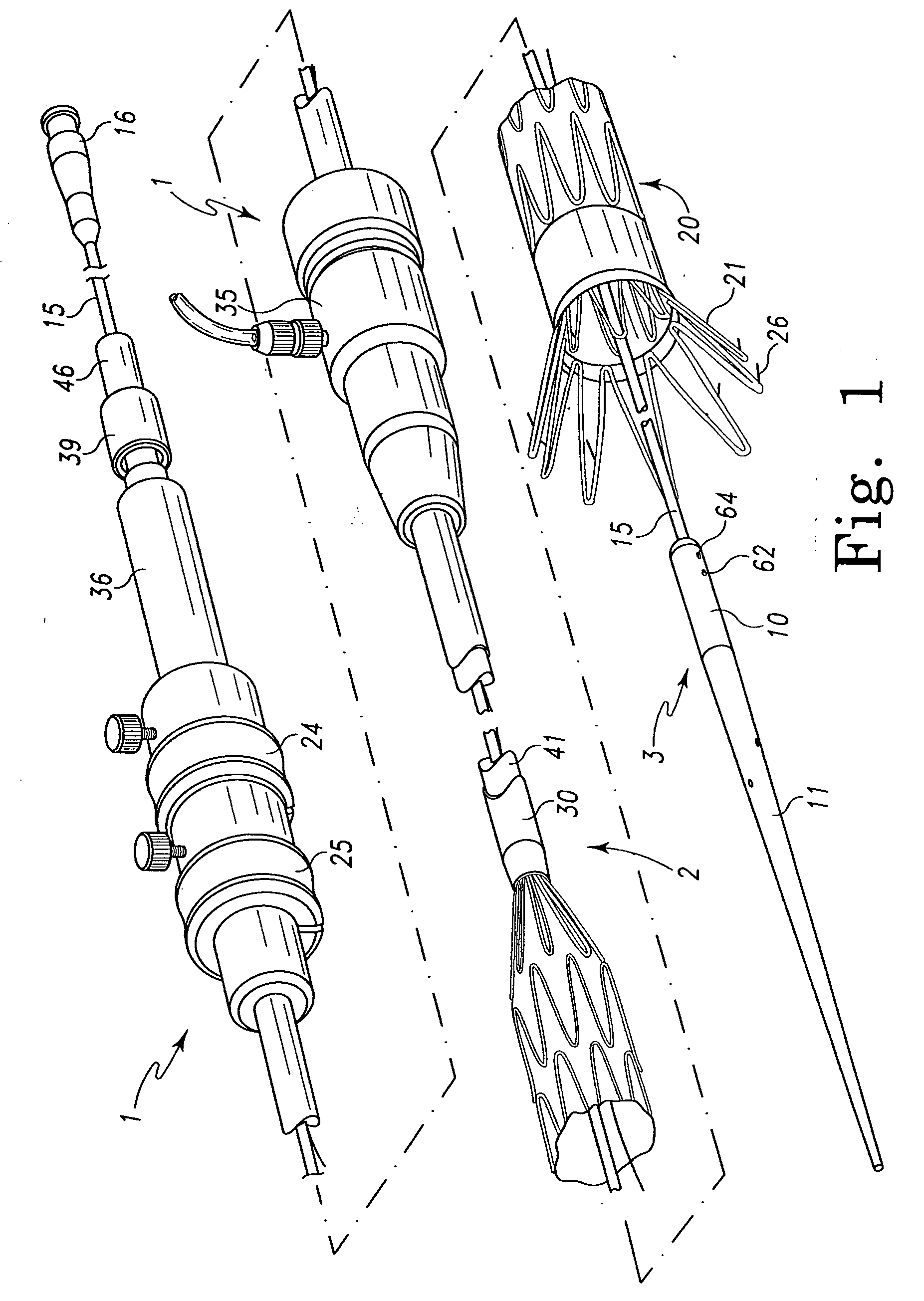
[0044]FIG. 1 shows a delivery system for an intraluminal medical device; in particular, a system for delivering and deploying an intraluminal prosthesis 20 in a lumen of a patient during a medical procedure. The system includes an external manipulation section 1, a proximal positioning mechanism or attachment region 2, and a distal positioning mechanism or attachment region3. During a medical procedur...


PUM


Abstract

A delivery system for an intraluminal medical device is disclosed. The delivery system comprises an elongate tubular sheath and an elongate tubular pusher. The pusher is slidably disposed within a lumen of the sheath and comprises at least one generally helical score in an exterior surface thereof for providing enhanced flexibility to the pusher.

Description

RELATED APPLICATIONS[0001]This application claims the benefit of the filing date under 35 U.S.C. §119(e) of U.S. Provisional Patent Application Ser. No. 60 / 779,815, filed Mar. 7, 2006, which is incorporated herein by reference.BACKGROUND OF THE INVENTION[0002]1. Field of the Invention[0003]This invention relates to a medical device and, in particular, to a system for delivering a medical device.[0004]2. Description of Related Art[0005]The deployment of a medical device, such as an intraluminal prosthesis, into the lumen of a patient from a remote location by the use of a delivery device is generally known. Radially-expandable prostheses can be used, for example, to repair diseased and damaged aorta such as abdominal aortic aneurysms and thoracic aortic aneurysms. For example, a stent-graft may be loaded onto a delivery and deployment device and percutaneously inserted into the body lumen of a patient in a radially-compressed configuration. Once the prosthesis is in a proper position...

Claims


Application Information

Patent Timeline
IPC IPC(8): A61F2/84
CPCA61F2/95A61F2250/0029A61F2002/9517A61F2002/9511A61F2/9517
Inventor BOWE, JASON SAMUEL-HORNER
Owner MED INST INC
Why Eureka
Try Eureka