Electric Wire or Cable

Inactive Publication Date: 2013-09-12
YAZAKI CORP
View PDF3 Cites 5 Cited by
  • Summary
  • Abstract
  • Description
  • Claims
  • Application Information

AI Technical Summary

Benefits of technology

[0054]In FIGS. 1, 2, 4 and 5, the insulator 3 is formedby extrusion coating to the outside of the conductor 2. As a material of the insulator 3, PP is used herein. However, it is not limited thereto. That is to say, it is possible to use known insulator materials which can be used as wire coating materials.
[0055]A wire harness can be formed by bundling the plural electric wires 1. Further, a cable can be formed by coating the outside of the insulator 3 with a sheath. The wire harness or cable is formed by a conventional method. The wire harness or cable including the electric wires 1 can be arranged around a hinge of a door or a trunk in an automobile (applicable to vario

Problems solved by technology

Copper is excellent in terms of tensile strength and electric conductivity as the material, but has a problem of heavy weight (density).
Aluminum is light in weight, but has a problem of insufficient strength.
Further, aluminum also has a problem of low flexibility compared to copper.
For example, in the

Method used


Image

  • Electric Wire or Cable
  • Electric Wire or Cable
  • Electric Wire or Cable

Examples


Example

Example 1

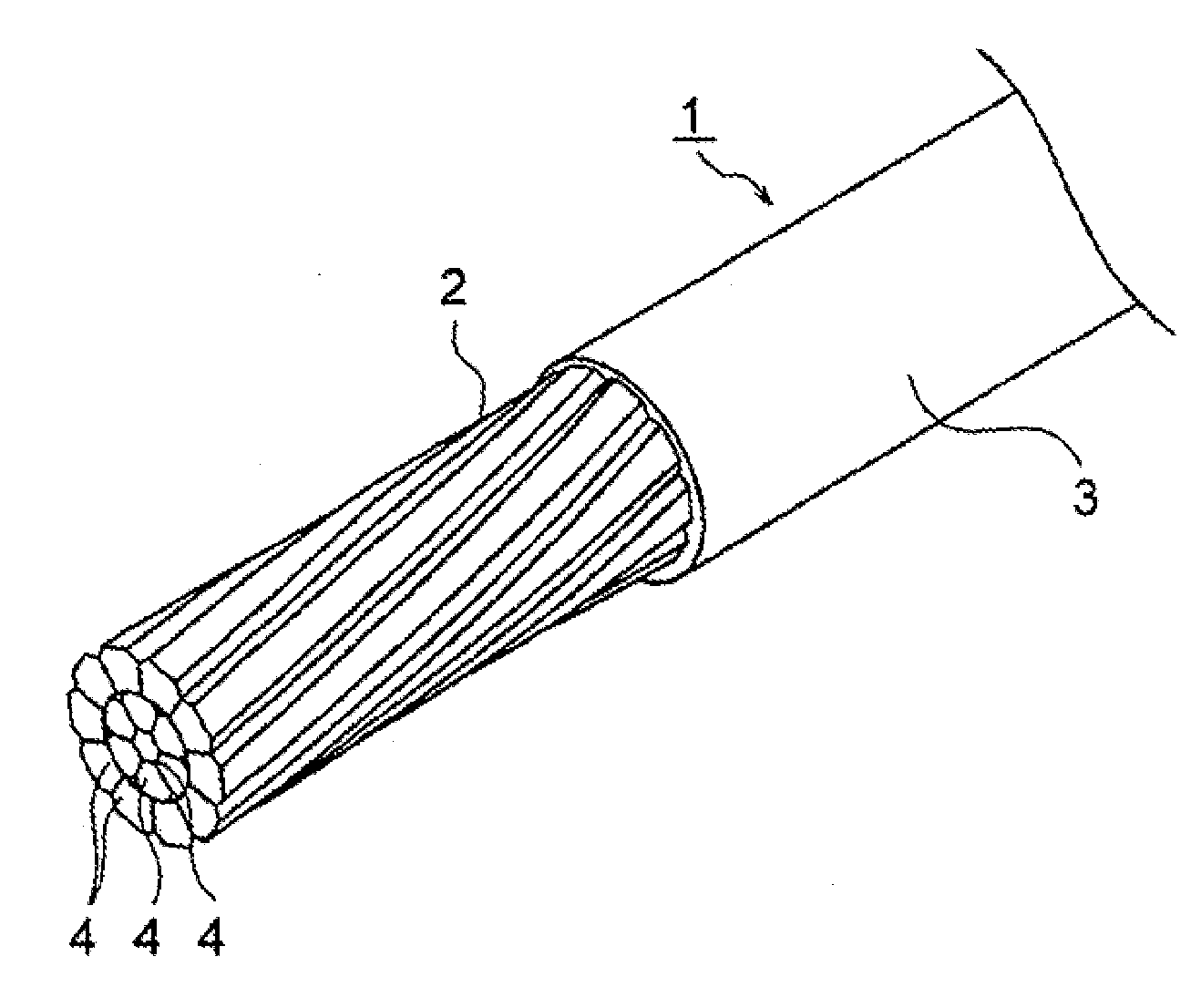
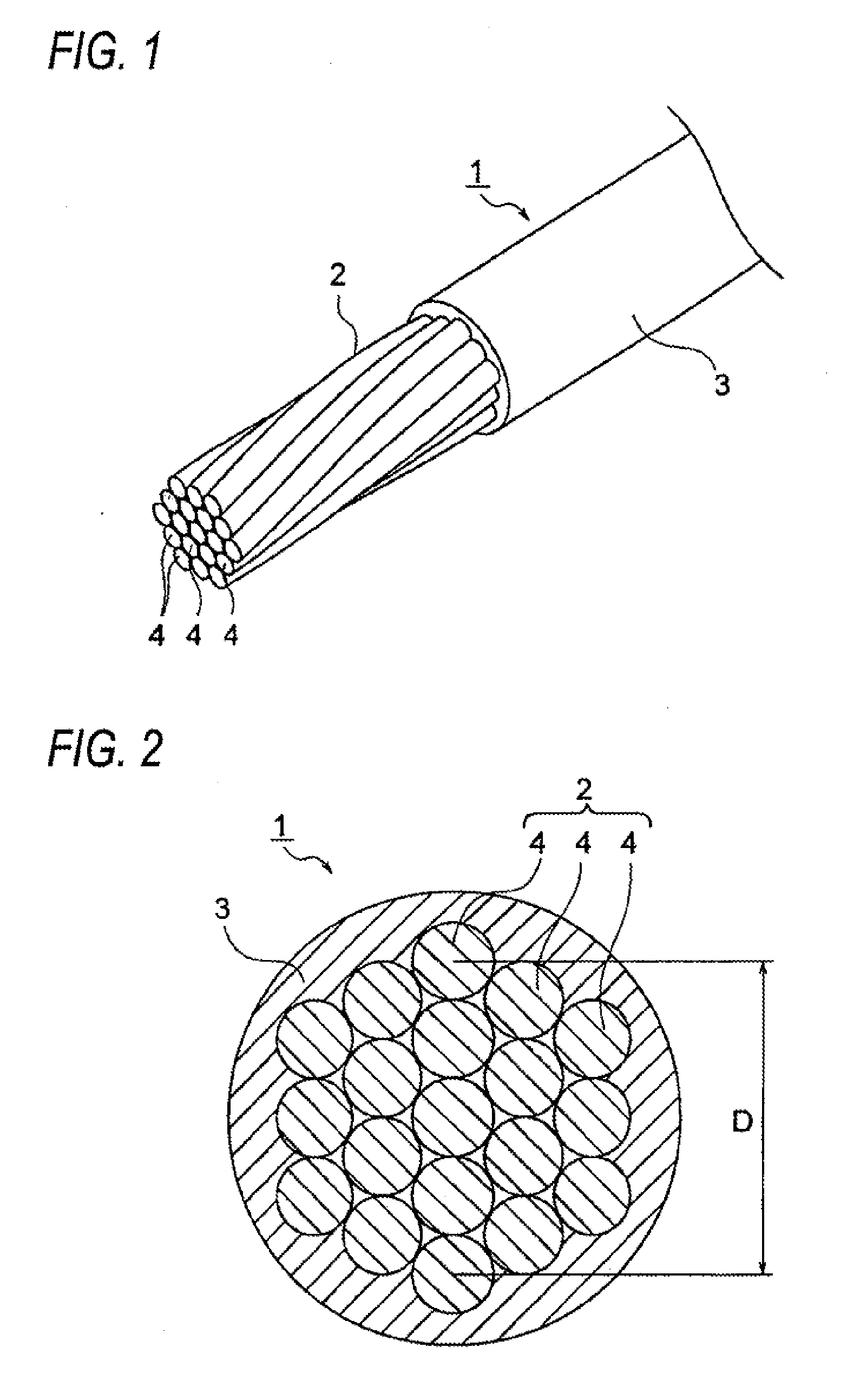
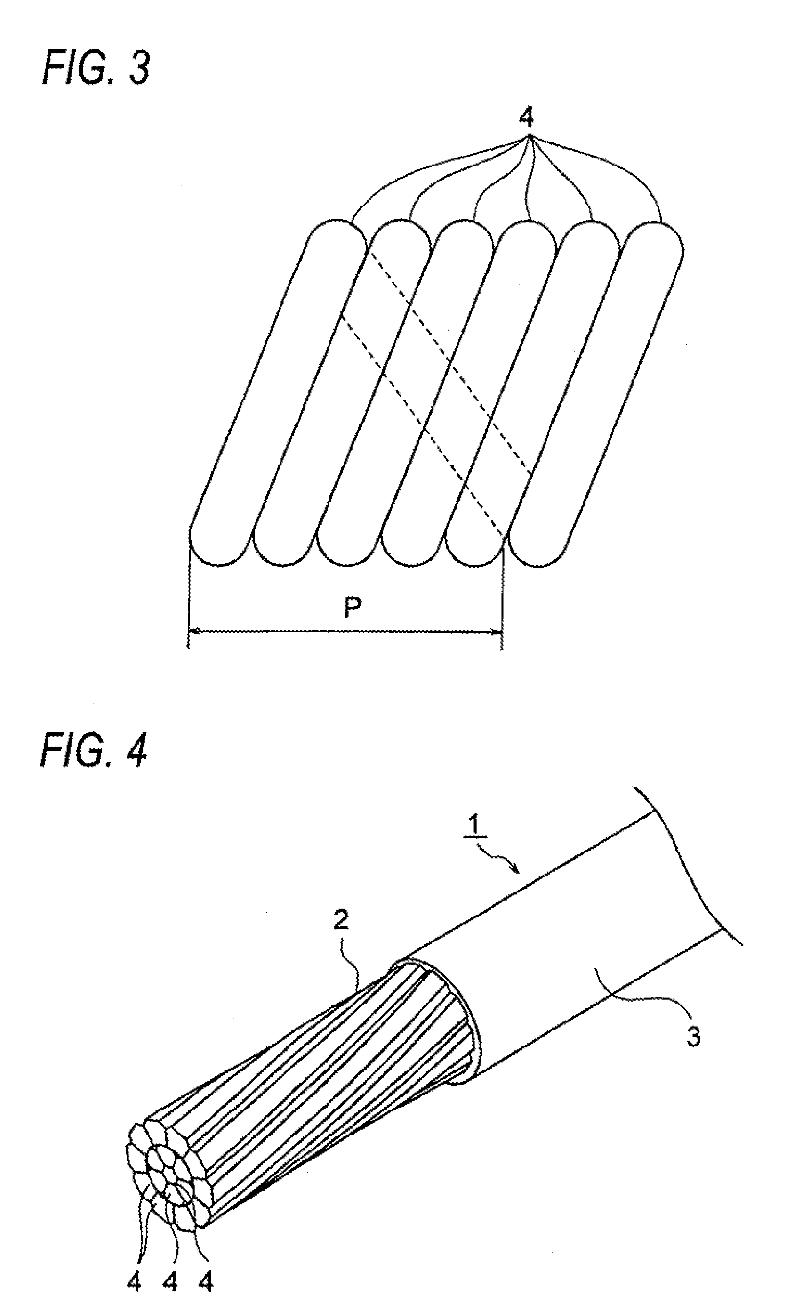
[0066]In Example 1, an aluminum alloy containing 0.02% by weight of Zr, 0.1% by weight of Fe, 0.02% by weight of Si and 0.06% by weight of Cu, with the remainder being Al and unavoidable impurities, is formed into aluminum alloy wires. By using the aluminum alloy having such a composition, an electric conductivity of 60.6% IACS, a tensile strength of 81 MPa and an elongation of 28% are obtained, the disconnection property becomes “good”, and the composition judgment becomes “good”. Further, in Example 1, a compact conductor is formed with a twist pitch of 14 times a diameter thereof. An electric wire formed using such a conductor has a number of flexing cycles of 2835, the judgment of the number of flexing cycles becomes “good”, and the overall judgment becomes “good”.

Example

Example 2

[0067]In Example 2, an aluminum alloy containing 0.02% by weight of Zr, 0.1% by weight of Fe, 0.02% by weight of Si and 0.03% by weight of Mg, with the remainder being Al and unavoidable impurities, is formed into aluminum alloy wires. By using the aluminum alloy having such a composition, an electric conductivity of 60.8% IACS, a tensile strength of 80 MPa and an elongation of 29% are obtained, the disconnection property becomes “good”, and the composition judgment becomes “good”. Further, in Example 2, a compact conductor is formed with a twist pitch of 14 times a diameter thereof. An electric wire formed using such a conductor has a number of flexing cycles of 2384, the judgment of the number of flexing cycles becomes “good”, and the overall judgment becomes “good”.

Example

Example 3

[0068]In Example 3, an aluminum alloy containing 0.08% by weight of Zr, 0.1% by weight of Fe, 0.02% by weight of Si and 0.06% by weight of Cu, with the remainder being Al and unavoidable impurities, is formed into aluminum alloy wires. By using the aluminum alloy having such a composition, an electric conductivity of 58.2% IACS, a tensile strength of 82 MPa and an elongation of 24% are obtained, the disconnection property becomes “good”, and the composition judgment becomes “good”. Further, in Example 3, a compact conductor is formed with a twist pitch of 14 times a diameter thereof. An electric wire formed using such a conductor has a number of flexing cycles of 2954, the judgment of the number of flexing cycles becomes “good”, and the overall judgment becomes “good”.


PUM


Abstract

An electric wire includes a conductor obtained by twisting together aluminum alloy wires. The conductor is formed with a conductor twist pitch of 7 to 36 times a predetermined diameter thereof, and a composition of an aluminum alloy before formation of the aluminum alloy wires contains 0.1 to less than 1.0% by weight of Fe, 0 to 0.08% by weight of Zr, 0.02 to 2.8% by weight of Si, and 0.05 to 0.63% by weight of Cu and/or 0.03 to 0.45% by weight of Mg, with the remainder being Al and unavoidable impurities.

Description

CROSS REFERENCE TO RELATED APPLICATION[0001]This application is a continuation of PCT application No. PCT / JP2011 / 075018, which was filed on Oct. 25, 2011 based on Japanese Patent Applications No. 2010-238196 filed on Oct. 25, 2010, the contents of which are incorporated herein by reference.BACKGROUND OF THE INVENTION[0002]1. Technical Field[0003]The present invention relates to an electric wire or cable including a conductor obtained by twisting together aluminum alloy wires.[0004]2. Background Art[0005]Copper has hitherto been mainly used as a conductor material of electric wires used in automotive wire harnesses and the like. Copper is excellent in terms of tensile strength and electric conductivity as the material, but has a problem of heavy weight (density). Accordingly, with a recent demand for weight reduction, a trend toward reconsideration of the conductor material has appeared. In such a situation, it has been particularly studied to use aluminum.[0006]Aluminum is light in ...

Claims


Application Information

Patent Timeline
IPC IPC(8): H01B1/02
CPCH01B7/0009H01B1/023
Inventor ISHIBASHI, KENICHIMOCHIZUKI, KAZUMIKONDO, YASUNOBU
Owner YAZAKI CORP
Why Eureka
Try Eureka