Thin film switch with changeable outlet joint

Inactive Publication Date: 2007-10-18
JENSIN INTL TECH CORP
View PDF5 Cites 6 Cited by
  • Summary
  • Abstract
  • Description
  • Claims
  • Application Information

AI Technical Summary

Benefits of technology

[0009]Accordingly, the present invention is directed to a thin film switch with a changeable outlet joint, so as to enhance the

Problems solved by technology

In addition, since the specifications of the thin film switches designed by various manufacturers are different, diversified thin film switch products are provided by thin film switch suppliers, a

Method used


Image

  • Thin film switch with changeable outlet joint
  • Thin film switch with changeable outlet joint
  • Thin film switch with changeable outlet joint

Examples


Example

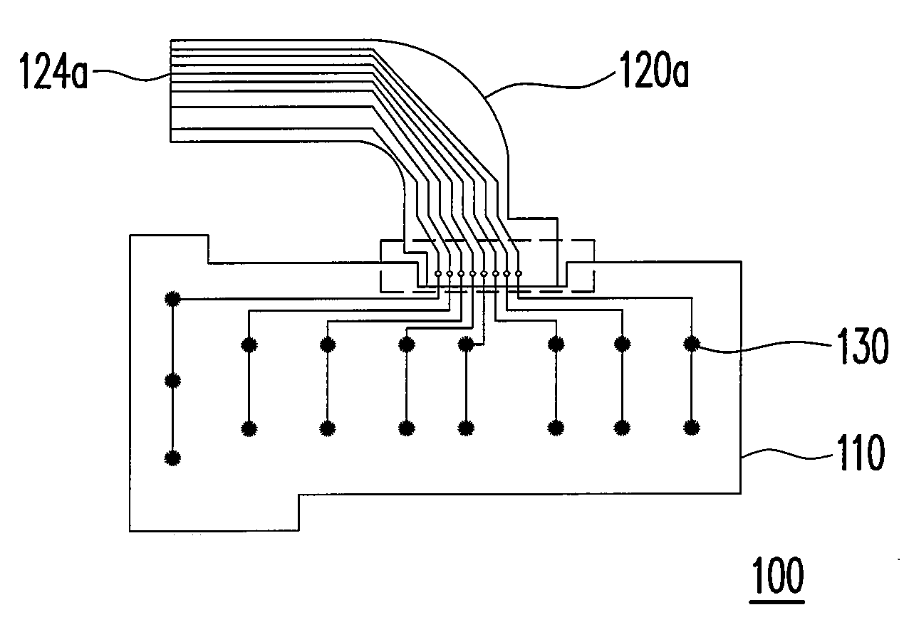
[0036]FIG. 3A is a view of the thin film switch 100 with a changeable outlet joint according to an embodiment of the present invention. The thin film switch 100 with a changeable outlet joint includes a thin film switch body 110 and a soft flat cable 120a, wherein the thin film switch body 110 includes a plurality of touch units 130. FIG. 3B is an exploded view of the thin film switch body 110 and the soft flat cable 120a of FIG. 3A. Referring to FIG. 3B, after the soft flat cable 120a is connectably disposed on an outlet end 112 of the thin film switch body 110 through a connecting portion 122a, the end 124a of the soft flat cable 120a as shown in FIG. 3A is formed. The soft flat cable 120a can be a conventional thin film flat cable or a flexible printed circuit board. In the present invention, the material of the soft flat cable 120a is the same as that of the thin film switch and may be also be fabricated by the same process. The connecting portion 122a may be a binding material ...


PUM


Abstract

A thin film switch with a changeable outlet joint includes two thin films, a touch circuit, and a soft flat cable. The two thin films have two opposite inner surfaces. The touch circuit includes a plurality of touch portions and an outlet end, which are disposed on the two opposite inner surfaces of the two thin films. Each couple of the touch portions switches to a conducting state when receiving a press action and transfers a signal to the outlet end. The soft flat cable includes a connecting portion. The soft flat cable is connectably disposed on the outlet end through the connecting portion to form an outlet joint.

Description

CROSS-REFERENCE TO RELATED APPLICATION[0001]This application claims the priority benefit of Taiwan application serial no. 95113603, filed Apr. 17, 2006. All disclosure of the Taiwan application is incorporated herein by reference.BACKGROUND OF THE INVENTION[0002]1. Field of the Invention[0003]The present invention relates to a thin film switch. More particularly, the present invention relates to a thin film switch with a changeable outlet joint.[0004]2. Description of Related Art[0005]A thin film switch has a plurality of touch portions disposed on the inner surfaces of two opposite thin films respectively, and each couple of opposite touch potions touches each other under an external compression to conduct a circuit, thereby achieving a desired switch function to generate a signal. After being connected with circuits, several sets of thin film switches are able to be combined into a set of input device as a printed circuit board (PCB) of a notebook PC keyboard.[0006]FIG. 1A is a sc...

Claims


Application Information

Patent Timeline
IPC IPC(8): G09G5/00H01H9/00
CPCH01H11/0031H01H13/702H01H2207/004H01H2231/002H01H2207/038H01H2229/038H01H2207/008
Inventor HSU, FENG-TING
Owner JENSIN INTL TECH CORP
Why Eureka
Try Eureka