Electro-Hydraulic Forming Tool Having Two Liquid Volumes Separated by a Membrane

Inactive Publication Date: 2008-06-12
FORD GLOBAL TECH LLC
View PDF11 Cites 24 Cited by
  • Summary
  • Abstract
  • Description
  • Claims
  • Application Information

AI Technical Summary

Benefits of technology

[0015]Other features of the electro-hydraulic forming tool may comprise a vessel vacuum port that opens into the vessel adjacent to the opening in the vessel and is ported to a source of vacuum. Proper air evacuation provides significant improvement of pressure transmitting efficiency from the discharge area to the blank surface. A vacuum port may also be provided that extends through the second cavity and opens into the

Problems solved by technology

Any air bubbles on the surface of the blank at the time the shockwave is propagated may cause surface defects in the formed part.
One disadvantage of electro-hydraulic forming is that each discharge of the electrodes to create the high voltage discharge in the fluid results in the formation of impurities in the water that results in vaporization of the electrodes.
The impurities in the fluid may be projected by the shockwave toward the blank and may create surface defects in the surface of the part formed in the process.
Another disadvantage of conventional electro-hydraulic form

Method used


Image

  • Electro-Hydraulic Forming Tool Having Two Liquid Volumes Separated by a Membrane
  • Electro-Hydraulic Forming Tool Having Two Liquid Volumes Separated by a Membrane
  • Electro-Hydraulic Forming Tool Having Two Liquid Volumes Separated by a Membrane

Examples


Embodiment Construction

)

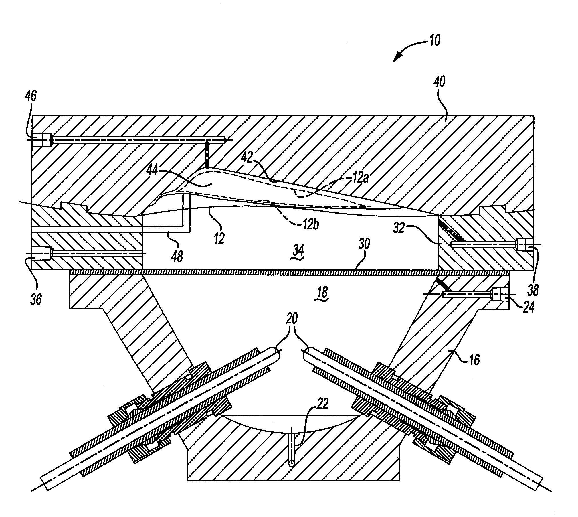
[0023]Referring to FIG. 1, an electro-hydraulic forming tool is generally indicated by reference numeral 10. The electro-hydraulic forming tool 10 is used to form a blank 12 of sheet metal into a desired shape.

[0024]The electro-hydraulic forming tool 10 includes a vessel 16 that defines a chamber 18. At least one pair of electrodes 20 is provided within the chamber 18. A liquid fill / drain part 22 is provided in the base of the vessel 16 through which a fluid, such as water, may be supplied or drained from the chamber 18 in the vessel 16.

[0025]An air evacuation port 24 is provided in the vessel 16 to evacuate air from the vessel 16. A membrane 30 is secured to the vessel 16 by a blank holder 32. The vessel 16 and blank holder 32 are secured together by means of conventional fasteners, as is well known in the art. The air evacuation port 24 permits removal of air or other gases that may accumulate on the bottom surface of the membrane 30 which could interfere with the operation of th...


PUM

PropertyMeasurementUnit
Timeaaaaaaaaaa
Volumeaaaaaaaaaa
Electric potential / voltageaaaaaaaaaa

Abstract

An electro-hydraulic forming tool is disclosed in which a membrane is retained between two volumes of liquid that are separated by a membrane. Electrodes are provided with a high voltage impulse to create a shockwave in one of the volumes of fluid that is transferred through the membrane to the other volume of fluid. The shockwave is transmitted to a blank that is formed into a one-sided die. The blank is formed against the forming surface of the die. Air evacuation means are provided to remove air from the upper surface of one or both volumes of liquid.

Description

BACKGROUND OF THE INVENTION[0001]1. Field of the Invention[0002]The present invention relates to an electro-hydraulic forming tool and a method of forming a sheet metal blank in an electro-hydraulic forming operation.[0003]2. Background Art[0004]Electro-hydraulic forming tools and processes produce a shockwave by creating a high voltage discharge in a liquid that is in contact with the sheet metal blank to be formed. The shockwave in the liquid is propagated towards the blank and causes the blank to be deformed into an open die that has a forming surface. The shockwave forces the blank into engagement with the forming surface to form the metal blank into the desired shape.[0005]Prior art electro-hydraulic forming tools have a liquid containing vessel that has an opening on its lower end. A blank holder is provided to hold a blank into engagement with the lower end of the vessel. By providing the vessel on top of the blank, air bubbles do not tend to form on the blank that could inte...

Claims


Application Information

Patent Timeline
IPC IPC(8): B21D26/00
CPCY10T29/49805B21D26/12
Inventor GOLOVASHCHENKO, SERGEYMAMUTOV, VYACHESLAVILINICH, ANDREY
Owner FORD GLOBAL TECH LLC
Why Eureka
Try Eureka