A high-temperature pressurization device for oil and gas well interlayer explosion propagation

A technology for pressurizing device and oil and gas wells, which is applied in wellbore/well components, production fluids, earthwork drilling, etc., to achieve the effects of reducing labor, convenient use and improving reliability

Active Publication Date: 2018-11-02
WUHUA ENERGY TECH CO LTD
View PDF17 Cites 0 Cited by
  • Summary
  • Abstract
  • Description
  • Claims
  • Application Information

AI Technical Summary

Problems solved by technology

[0005] The technical problem solved by the present invention is: to overcome the above-mentioned problems existing in the existing multi-stage perforation in the petroleum industry, and at the same time, to avoid the shortcomings of the prior art, to provide a high-temperature pressurized device for interlayer explosion transmission in oil and gas wells, which solves the problem of large The problem of detonation transmission in multi-layered and large-span perforation in inclined wells and horizontal wells, simplifies the construction process, improves the reliability of construction in long interlayers, eliminates hidden dangers of accidents, and meets the requirements of oilfields for the safety, reliability and economy of perforating equipment. Environmental requirements

Method used


Image

  • A high-temperature pressurization device for oil and gas well interlayer explosion propagation
  • A high-temperature pressurization device for oil and gas well interlayer explosion propagation
  • A high-temperature pressurization device for oil and gas well interlayer explosion propagation

Examples


Embodiment Construction

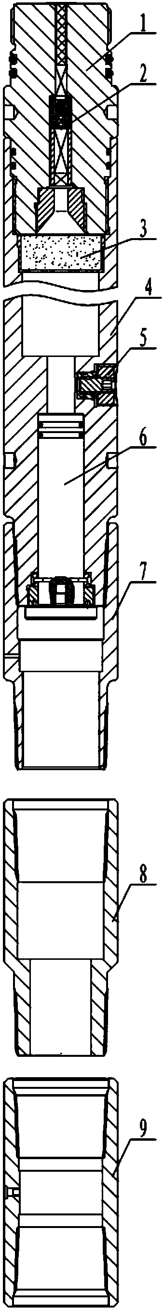
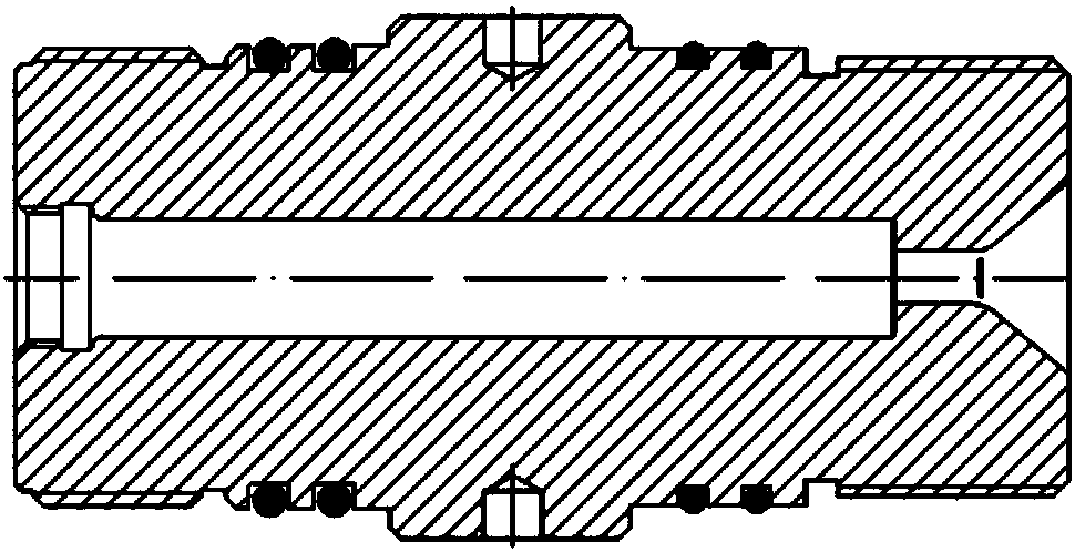
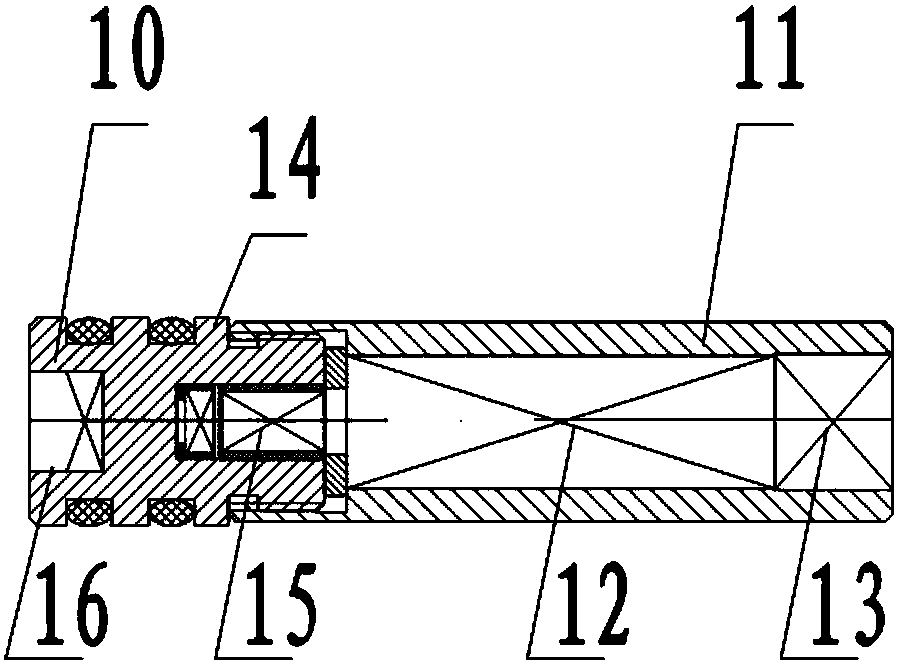
[0042] see Figure 1 to Figure 8 , a high-temperature supercharging device for oil and gas well interlayer explosion transmission, including the following process: the supercharging device is connected to the tail of the upper-stage perforating gun, and the small hole collar in the supercharging device is connected to the At the output end of the main body, connect a 2-10m interlayer oil pipe after the small hole collar, and then connect the limit collar, connect several interlayer oil pipes after the limit collar, and connect the end of the last interlayer oil pipe to the supercharging device. The large hole collar, the output end of the big hole collar is connected with the pressure detonation device and the perforating gun of the next stage. When the upper-stage perforating gun connected to the booster device is detonated, the perforating gun transmits the detonation wave to the booster joint, detonates the diaphragm igniter in the booster device joint, and the diaphragm ig...


PUM


Abstract

The invention discloses a high-temperature supercharging device for interlayer explosion transmission in oil and gas wells. The joint and the body are fixedly connected by threads, the ignition assembly of the diaphragm is placed in the through hole of the joint, and the gunpowder assembly and the piston assembly are respectively placed on both sides of the combustion chamber of the body. The pressure relief valve is placed on the side of the combustion chamber of the main body, and the main body and the first coupling are fixedly connected by oil pipe threads, and a certain number of oil pipes are used to connect the first coupling, the second coupling and the third coupling. The invention can solve the interlayer detonation transmission problem in multi-layer section and long-span perforation construction of highly inclined wells and horizontal wells, and uses the detonation wave generated after the normal detonation of the upper-level perforating gun to act on the diaphragm to ignite Then ignite the gunpowder assembly, and instantly generate high-temperature and high-pressure gas in the combustion chamber of the main body, push out the piston assembly in the main body at high speed, and transmit the gas pressure to the next-level pressure type detonation instantly by compressing the clean water killing fluid in the interlayer tubing On the device, the detonation operation of the next-level perforating gun is completed.

Description

technical field [0001] The invention belongs to the technical field of oil and gas well perforation, and mainly relates to an oil and gas well (TCP) tubing transmission perforation interlayer detonation technology, in particular to a high-temperature booster device for oil and gas well interlayer detonation transmission. Background technique [0002] In the petroleum industry, oil well perforation operation is an important process, which is to lower the perforating gun into the target layer in the well, use the detonating device to detonate, and after detonation, the shaped charge will penetrate the perforating gun, casing and cement layer. The exit channel connects the stratum with the oil well, so that the formation oil and gas can flow into the oil well smoothly. [0003] Multi-stage perforation technology refers to the perforation technology that penetrates multiple oil and gas layers at one time in the case of the next pipe string, which can reduce the number of perfora...

Claims


Application Information

Patent Timeline
Patent Type & Authority Patents(China)
IPC IPC(8): E21B43/1185E21B43/116
CPCE21B43/116E21B43/11852
Inventor 周曌杨伟同剑王峰程永峰胡咏梅刘帅闵杰张虎
Owner WUHUA ENERGY TECH CO LTD
Why Eureka
Try Eureka