Thermal Control for LED Backlight

Inactive Publication Date: 2008-06-12
MICROSEMI
View PDF31 Cites 191 Cited by
  • Summary
  • Abstract
  • Description
  • Claims
  • Application Information

AI Technical Summary

Benefits of technology

[0019]The invention provides for a backlighting system comprising: a controller; at least one luminaire comprising a plurality of LEDs; and at least one thermal sensor in communication with the controller, the controller being operative to control the luminance of the at least one luminaire responsive to th

Problems solved by technology

One known problem of LCD matrix displays is motion blur.
One cause of motion blur is that the response time of the LCD is finite, and additionally the LCD exhibits sample and hold characteristics.
Thus, there is a delay from the time of writing to the LCD pixel until the image changes.
Furthermore, since each pixel is written once per scan, and then is held until the next scan, smooth motion is not possible.
Unfortunately, as the effectiveness of optical partitions improve, thereby improving the operation of the scanning backlight and the matrix display as a whole, such a single sensor will not receive sufficient light from adjacent region

Method used


Image

  • Thermal Control for LED Backlight
  • Thermal Control for LED Backlight
  • Thermal Control for LED Backlight

Examples


Embodiment Construction

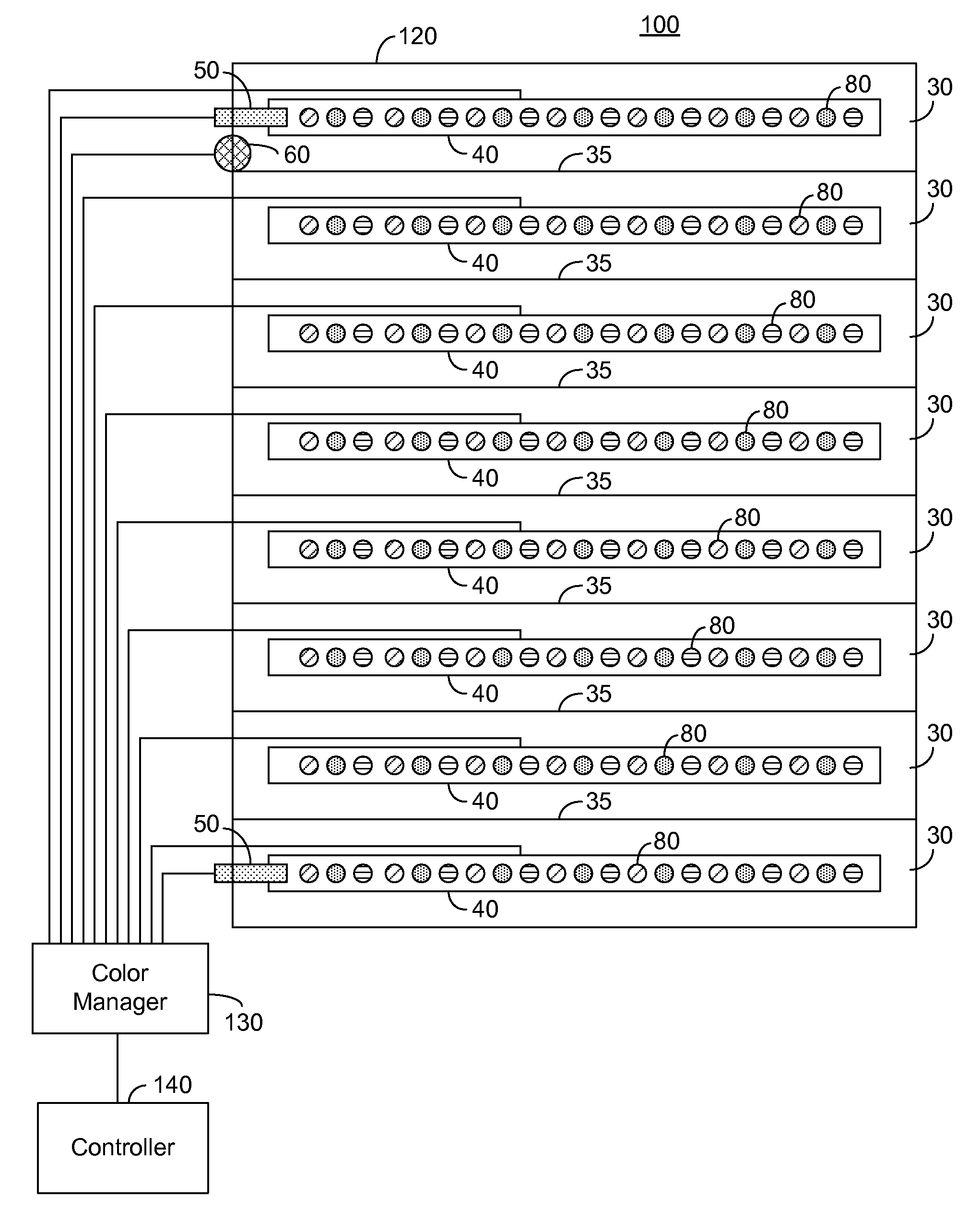
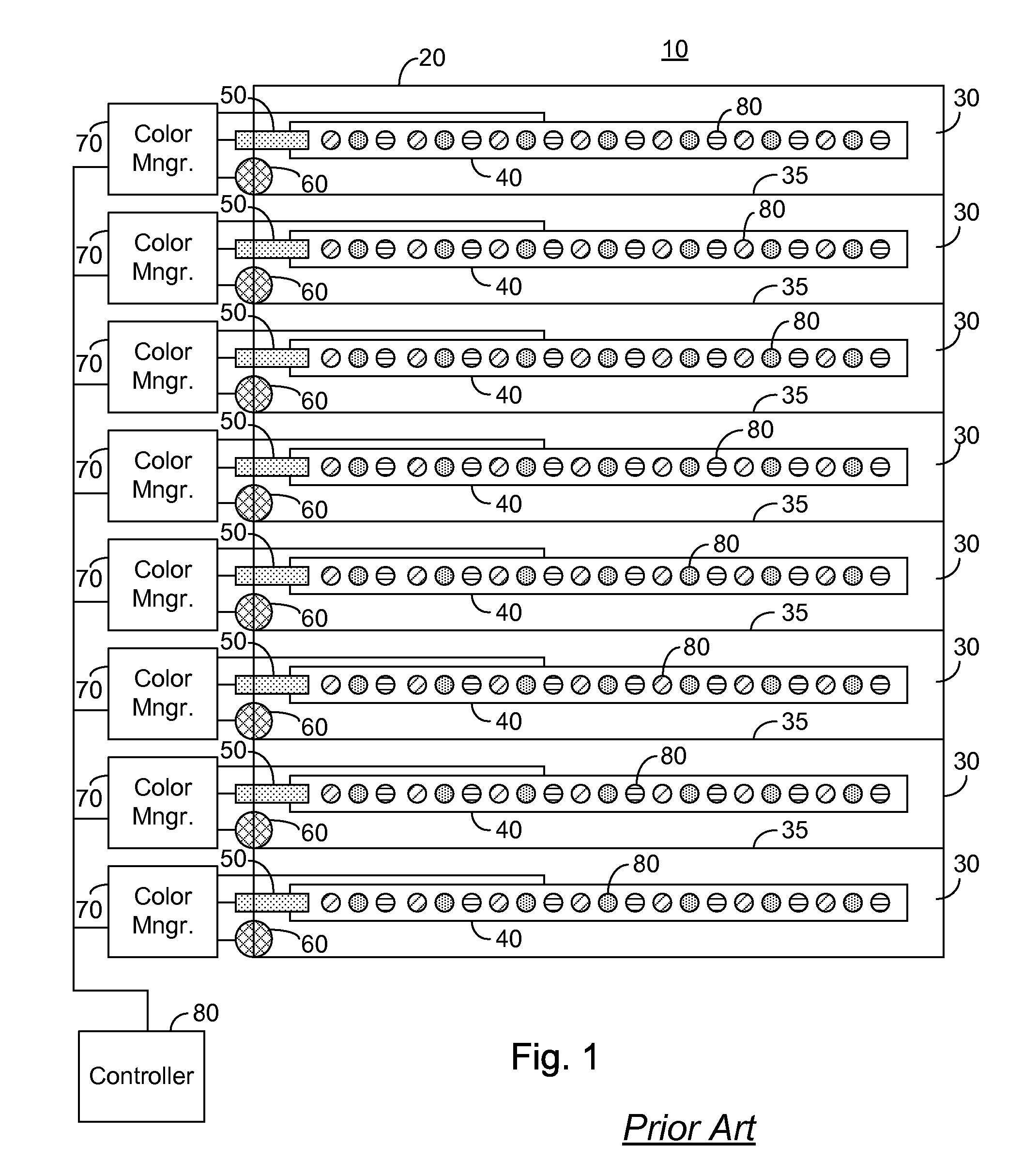
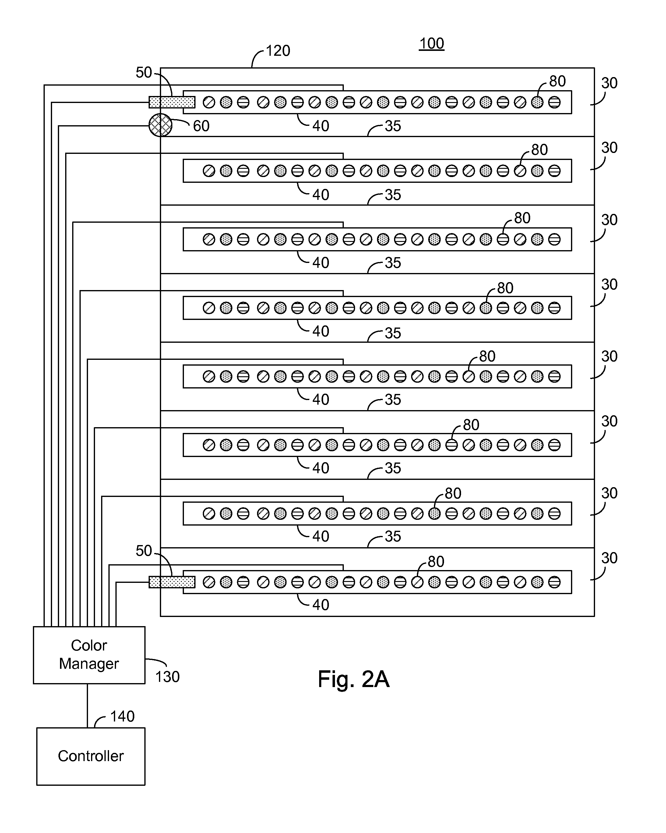
[0030]The present embodiments enable a backlighting system exhibiting a plurality of luminaires preferably arranged in a plurality of horizontally arranged regions. In one embodiment each of the luminaires comprises LED strings of a plurality of colors which in combination produce a white light. In another embodiment each of luminaires are constituted of LEDs of a single color, preferably white LEDs. Optical partitions are optionally further provided horizontally to limit any light spillover from a region to an adjacent region. At least two thermal sensors are further provided, the number of thermal sensors preferably being less than the number of regions. In an exemplary embodiment a thermal sensor is provided for the top region and the bottom region.

[0031]A controller receives the temperature indications from the thermal sensors and is operable to compare the temperature indications to a maximum temperature. In the event that the temperature has reached or exceeded the maximum tem...


PUM


Abstract

A backlighting system comprising: a controller; at least one luminaire comprising a plurality of LEDs; and at least one thermal sensor in communication with the controller, the controller being operative to control the luminance of the at least one luminaire responsive to the at least one thermal sensor. Preferably, the control of the luminance comprises: in the event that a temperature indication responsive to an output of the at least one thermal sensor is greater than a first pre-determined maximum, reducing the luminance of at least one of the at least one luminaire.

Description

CROSS-REFERENCE TO RELATED APPLICATIONS[0001]This application claims priority from U.S. Provisional Patent Application Ser. No. 60 / 868,943 filed Dec. 7, 2006, entitled “Thermal Control for LED Backlight”, the entire contents of which is incorporated herein by reference.BACKGROUND OF THE INVENTION[0002]The present invention relates to the field of light emitting diode based lighting and more particularly to a means of preventing thermal runaway in an LED based back light system.[0003]Light emitting diodes (LEDs) and in particular high intensity and medium intensity LED strings are rapidly coming into wide use for lighting applications. LEDs with an overall high luminance are useful in a number of applications including backlighting for liquid crystal display (LCD) based monitors and televisions, collectively hereinafter referred to as a matrix display. In a large LCD matrix display typically the LEDs are supplied in one or more strings of serially connected LEDs, thus sharing a commo...

Claims


Application Information

Patent Timeline
IPC IPC(8): G09G3/36
CPCG09G3/3413G09G3/342G09G2360/145G09G2320/041G09G2300/0443
Inventor PEKER, ARKADIYKORCHARZ, DRORFERENTZ, ALON
Owner MICROSEMI
Why Eureka
Try Eureka