Eureka AIR delivers breakthrough ideas for toughest innovation challenges, trusted by R&D personnel around the world.

Light-emitting diode and vehicular lamp

a technology of light-emitting diodes and vehicular lamps, which is applied in the direction of semiconductor devices for light sources, lighting and heating apparatus, instruments, etc., can solve the problems of inability to solve problems, lens arrangement cannot sufficiently mitigate the sharp luminance distribution of light-emitting diodes, and the inability to emit enough light. to achieve the effect of improving utilization efficiency

Active Publication Date: 2008-03-04
KOITO MFG CO LTD
View PDF26 Cites 82 Cited by
  • Summary
  • Abstract
  • Description
  • Claims
  • Application Information

AI Technical Summary

Benefits of technology

[0011]Accordingly, it is an object of the present invention to provide a vehicular light-emitting diode that has no such problems as seen in the conventional light-emitting diodes in which the luminance rapidly decreases according to the increase in the divergence angle centered on the optical axis.
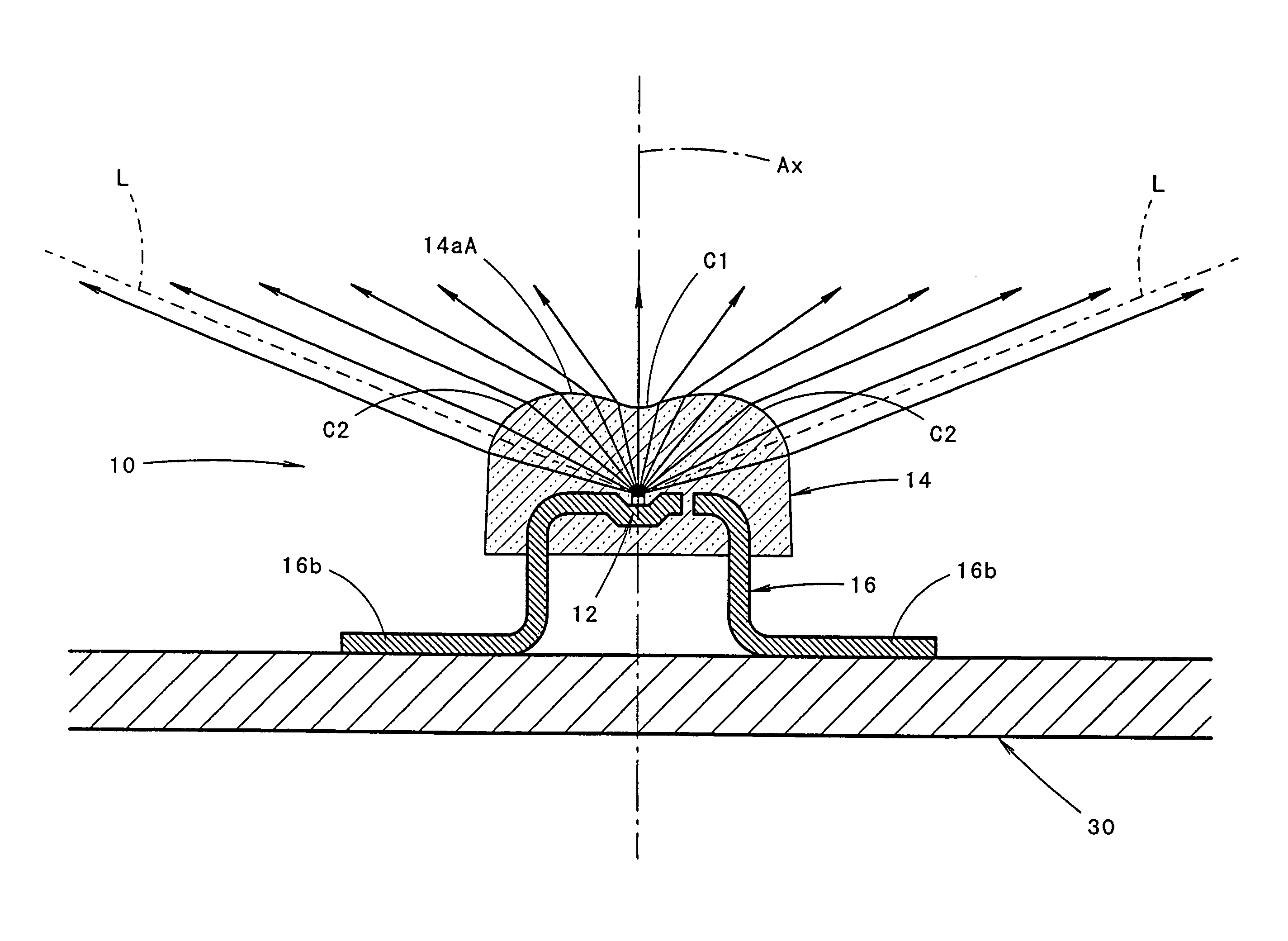
[0022]As seen from the above, in the structure of the present invention described above, the light-emitting diode of the present invention has a light-emitting chip disposed on a predetermined optical axis and a transparent sealing member that seals the light-emitting chip on the side that faces the forward direction along the optical axis; and further, sealing member has a curved surface portion on the front face. In addition, the cross-sectional shape of the curved surface portion taken along the first plane that includes the optical axis is formed by an undulating curve that has a concave curve positioned near the optical axis and convex curves positioned on both sides of the concave curve. This structure provides several advantages.
[0025]In the present invention, the curved surface portion of the sealing member can be formed in a shape created by rotating the undulating curve about the optical axis. This structure provides a luminance distribution of the light directed from the curved surface portion of the sealing member which exhibits a smooth increase in the luminance or exhibits a substantially uniform luminance distribution, from the direction along the optical axis up to the direction that has a predetermined divergence angle centered on the optical axis in any direction toward any portion of the perimeter with respect to the optical axis. As a result, even in a case that a large-size lens is provided in front of the light-emitting diode, it is possible to have the lens appear to be sufficiently illuminated up to the perimeter edge portions.
[0028]In the present invention, the perimeter of the curved surface portion of the front face of the sealing member can be formed with a deflection directing portion, which directs the light emitted from the light-emitting chip so that it is deflected toward the optical axis. This structure improves the utilization efficiency for the light emitted from the light-emitting chip.
[0029]In particular, in a case that the cross-sectional shape of the curved surface portion of the sealing member taken along the second plane is in a shape of a convex curve, a relatively large amount of light emitted from the light-emitting chip is directed toward either side of the convex curve, and this structure is markedly advantageous. In a case that the curved surface portion of the sealing member is formed in a bilobal shape that has a transversely narrowed part in the middle in the longitudinal direction of the bilobal shape when viewed from the front, a considerable amount of light emitted from the light-emitting chip is directed toward either side of the middle portion in the longitudinal direction, and this structure is also markedly advantageous.

Problems solved by technology

This, however, causes problems that such a light-emitting diode cannot radiate light with sufficient luminance in an oblique direction while the light-emitting diode radiates light with sufficient luminance in the forward direction.
When such light-emitting diodes as described above are used as a light source of a vehicular lamp, several problems occur.
However, when a light-emitting diode is used as a light source, such a lens arrangement cannot sufficiently mitigate the sharp luminance distribution of the light-emitting diode.
As a result, such a lamp radiates light with an extremely great intensity to the front of the lamp (which is so-called pin-point illumination), and this problem cannot be solved.
In this case, the light emitted from the light-emitting diode reaches the perimeter of the lens at a significantly wide incident angle, and this reduces the lens efficiency.
As a result, a further problem occurs that the light directed from the perimeter of the lens is significantly low in intensity as compared to the light directed from the center portion of the lens.

Method used


Image

  • Light-emitting diode and vehicular lamp
  • Light-emitting diode and vehicular lamp
  • Light-emitting diode and vehicular lamp

Examples


first embodiment

[0051]the present invention will be described first.

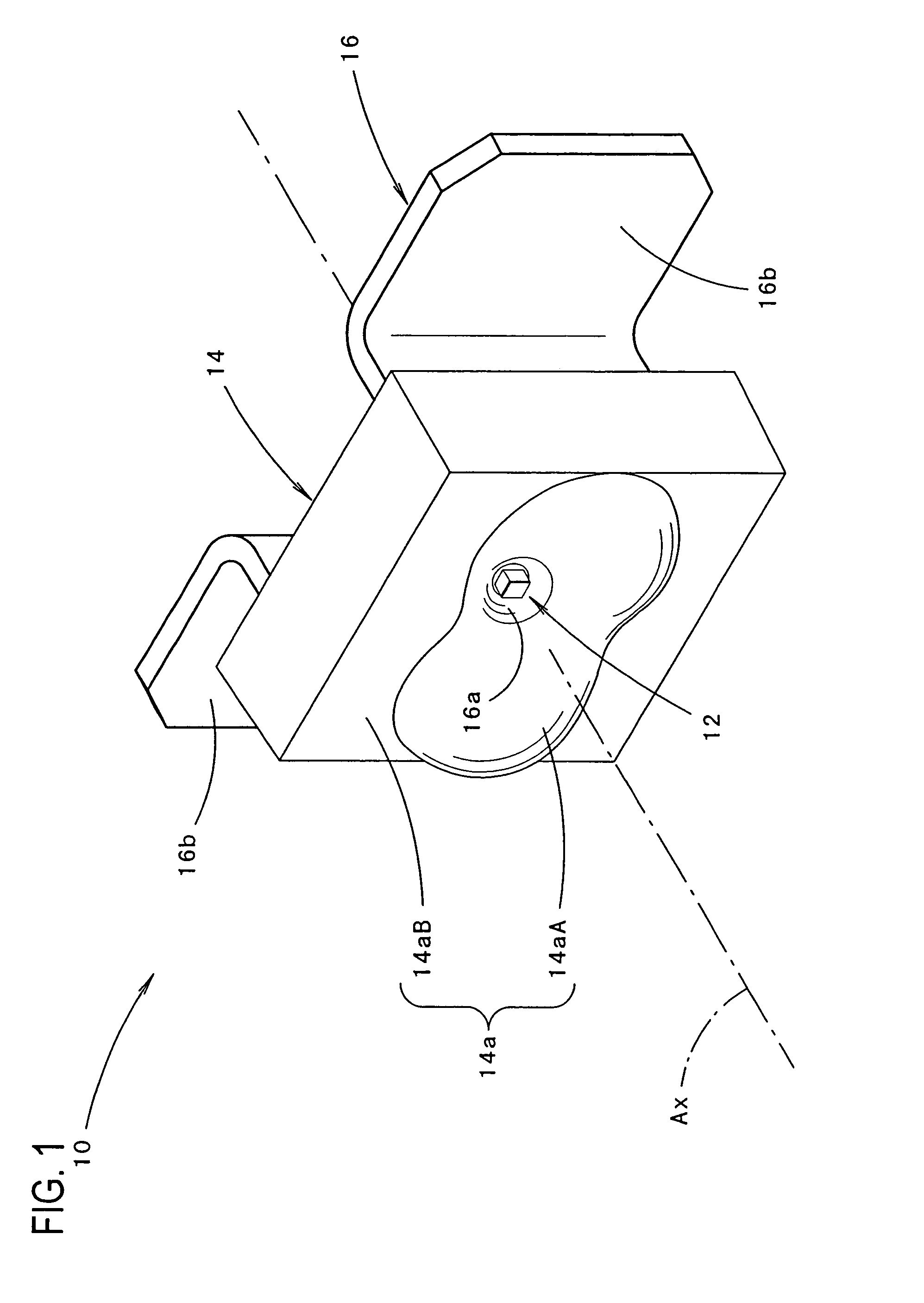
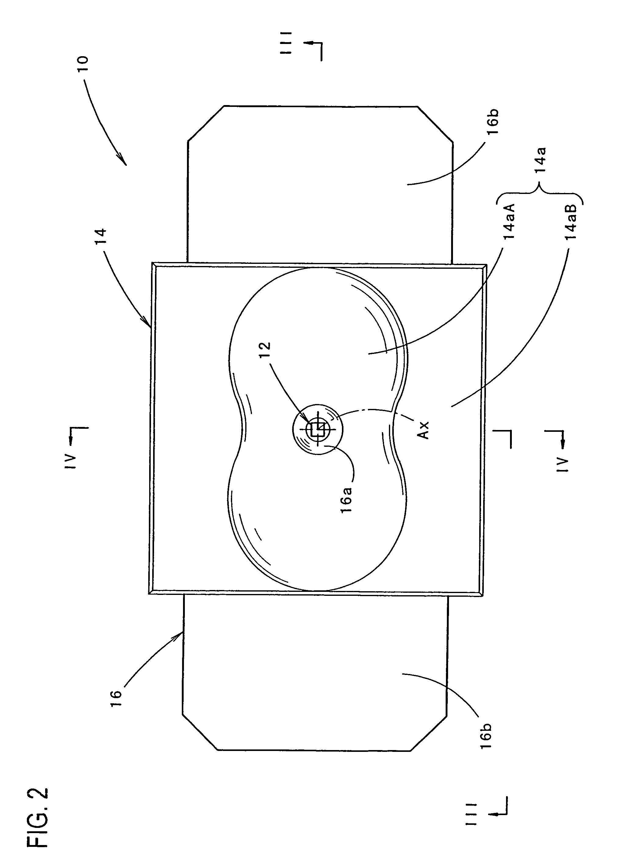
[0052]FIG. 1 is a perspective view of the light-emitting diode 10 according to the first embodiment, and FIG. 2 is a front view thereof. FIG. 3 and FIG. 4 are the cross-sectional views taken along the line III-III and line IV-IV in FIG. 2, respectively.

[0053]As seen from FIGS. 1 through 4, the light-emitting diode 10 is comprised of a light-emitting chip 12 disposed on a predetermined optical axis Ax, a transparent sealing member 14 that seals the light-emitting chip 12 on the side that faces the forward direction along the optical axis Ax (which will simply be referred to as “front side” hereafter), and a lead frame 16 for supporting the light-emitting chip 12.

[0054]The light-emitting chip 12 has a light emitting face of around 0.3 to 1 mm square and is disposed with its light emission center O positioned on the optical axis Ax and with its light emitting face facing toward the front face (i.e., in the forward direction along the ...

second embodiment

[0090]Next, the second embodiment according to the present invention will be described.

[0091]FIG. 12 is a perspective view of the light-emitting diode 110 of the second embodiment, and FIG. 13 is a front view thereof FIG. 14 and FIG. 15 are cross-sectional views taken along the line XIV-XIV and line XV-XV in FIG. 13, respectively.

[0092]As seen from FIGS. 12 through 15, the light-emitting diode 110 has the same basic configuration as that of the light-emitting diode 10 of the above-described first embodiment. The configuration of the front face 114a of the sealing member 114 of the light-emitting diode 110, however, differs from that of the first embodiment.

[0093]In other words, the front face 114a of the sealing member 114 is formed by a curved surface portion 114aA and a deflection directing portion 114aB.

[0094]The curved surface portion 114aA has entirely the same structure as that of the curved surface portion 14aA of the front face 14a in the sealing member 14 of the first embod...

third embodiment

[0098]Next, the present invention will be described below.

[0099]FIG. 16 shows a light-emitting diode 210 of the third embodiment.

[0100]As seen from FIG. 16, the light-emitting diode 210 has the same basic configuration as that of the light-emitting diode 10 of the first embodiment. The front face 214a of the sealing member 214 of the light-emitting diode 210, however, differs from that of the first embodiment.

[0101]In other words, the front face 214a of the sealing member 214 has a curved surface portion 214aA and a deflection directing portion 214aB.

[0102]The curved surface portion 214aA is formed as a surface of revolution, in which the undulating curve, which forms the cross-sectional shape of the curved surface portion 14aA of the front face 14a of the sealing member 14 taken along the horizontal plane that includes the optical axis Ax of the first embodiment, is rotated about the optical axis Ax.

[0103]The deflection directing portion 214aB is formed by a circular stepped portio...


PUM


Abstract

A light-emitting diode including a curved surface portion 14aA formed in the front face of a sealing member 14 with the cross-sectional shape of the curved surface portion being in the shape of an undulating curve that has a concave curve C1 near the optical axis and convex curves C2 on both sides of concave curve C1, thus allowing the light emitted from a light-emitting chip 12 at a small divergence angle centered on the optical axis Ax to reach the concave curve C1 and to be directed forward as diffused light deflected from the optical axis and further allowing the light emitted at a large divergence angle centered on the optical axis Ax to reach the convex curves C2 and to be directed forward as light deflected toward line L positioned at the divergence angle θ.

Description

BACKGROUND OF THE INVENTION[0001]1. Field of the Invention[0002]The present invention relates to a light-emitting diode in which a light-emitting chip is sealed by a transparent sealing member and to a vehicular lamp and more particularly to a structure of the sealing member of a light-emitting diode and to a vehicular lamp that uses such a light-emitting diode.[0003]2. Description of the Related Art[0004]In recent years, light-emitting diodes are used more often in vehicular lamps as its light source.[0005]Light-emitting diodes are generally comprised of, as disclosed in Japanese Patent Application Laid-Open (Kokai) No. 2001-283616, a light-emitting chip, which is disposed on a predetermined optical axis, and a transparent sealing member, which seals the front side of the light-emitting chip on the optical axis. The front face of the sealing member has a substantially spherical surface.[0006]Japanese Patent Application Laid-Open (Kokai) No. 2002-94129 discloses a light-emitting dio...

Claims


Application Information

Patent Timeline
Patent Type & Authority Patents(United States)
IPC IPC(8): H01L31/18H01L33/56F21V5/00F21Y101/02H01L33/58H01L33/60H01L33/62
CPCF21S48/1145F21S48/215G02B3/02F21V5/04F21Y2101/02H01L33/54F21Y2115/10F21S41/14F21S43/14H01L2924/181H01L2924/1815H01L2924/00012
Inventor AMANO, YASUYUKIMACHIDA, TSUTOMUKOIZUMI, HIROYA
Owner KOITO MFG CO LTD
Why Eureka
Eureka Blog
Learn More