Eureka AIR delivers breakthrough ideas for toughest innovation challenges, trusted by R&D personnel around the world.

Light distribution apparatus and methods for illuminating optical systems

a technology of optical system and light distribution apparatus, which is applied in the field of illumination devices and methods, can solve the problems of increasing the cost of many applications, increasing the size of products, and heavy weight, and achieves the effects of increasing divergence, increasing illuminance, and constant luminan

Active Publication Date: 2005-01-27
SYNOPSYS INC
View PDF54 Cites 83 Cited by
  • Summary
  • Abstract
  • Description
  • Claims
  • Application Information

AI Technical Summary

Benefits of technology

Another embodiment of the invention comprises a method of projecting an image on a rear projection TV, said method comprising: producing increasing illuminance at an input of an light distribution optics having a lateral spatial extent and an output with increasing numerical aperture across said lateral spatial extent; outputting light from said light distribution optics having increasing numerical aperture across said lateral spatial extent into increasingly large projected solid angles across said lateral spatial extent so as to reduce variation in luminance; directing said light with reduced variation in luminance to said spatial light modulator; forming a pattern with said spatial light modulator based on video or computer signals; propagating light from said spatial light modulator to imaging optics; and forming an image of said pattern formed by said spatial light modulator with said imaging optics onto said screen of said rear projection TV.
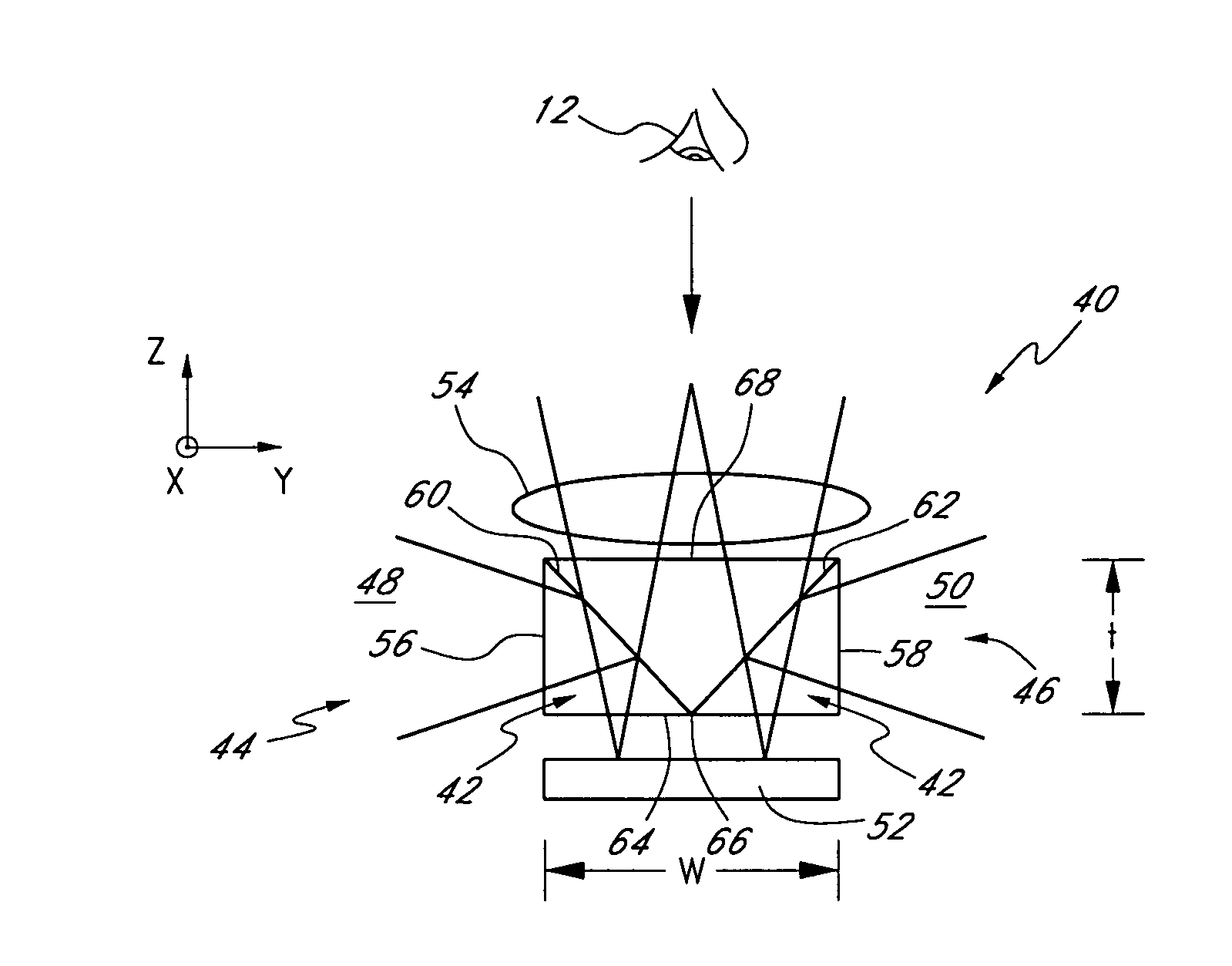
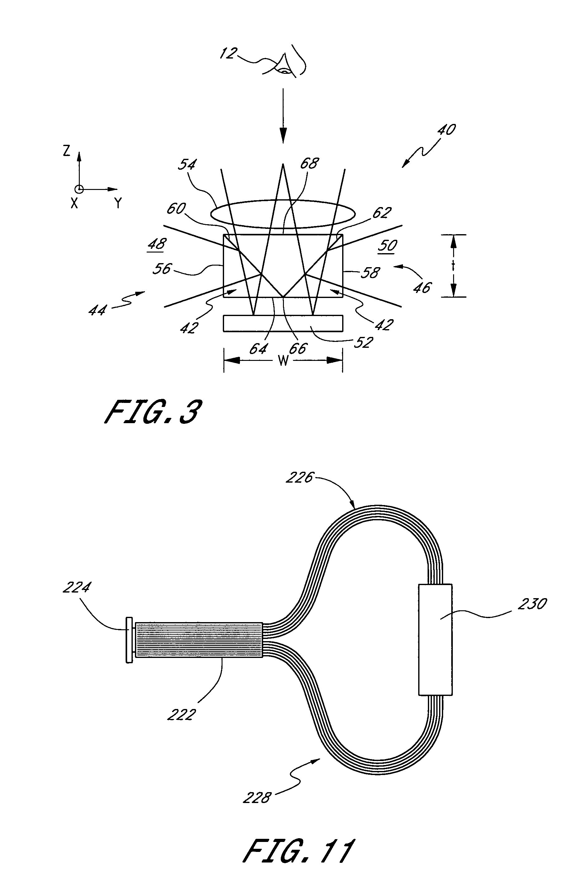
Another embodiment of the invention comprises a method of projecting an image onto a screen, said method comprising: forming a pattern with an array of modulators; illuminating an area of said array of modulators with illumination having substantially constant luminance across said area; imaging said area with imaging optics having a pupil and an F-number that varies across a dimension of said array of modulators, wherein said illumination at said array of modulators has (i) increasing divergence across said area so as to substantially fill said pupil with said variation in F-number without substantially overfilling and (ii) increasing illuminance across said area to provide substantially constant luminance.

Problems solved by technology

As many components are included in the optical systems, the products become larger, heavier, and more expensive than desired for many applications.

Method used


Image

  • Light distribution apparatus and methods for illuminating optical systems
  • Light distribution apparatus and methods for illuminating optical systems
  • Light distribution apparatus and methods for illuminating optical systems

Examples


Embodiment Construction

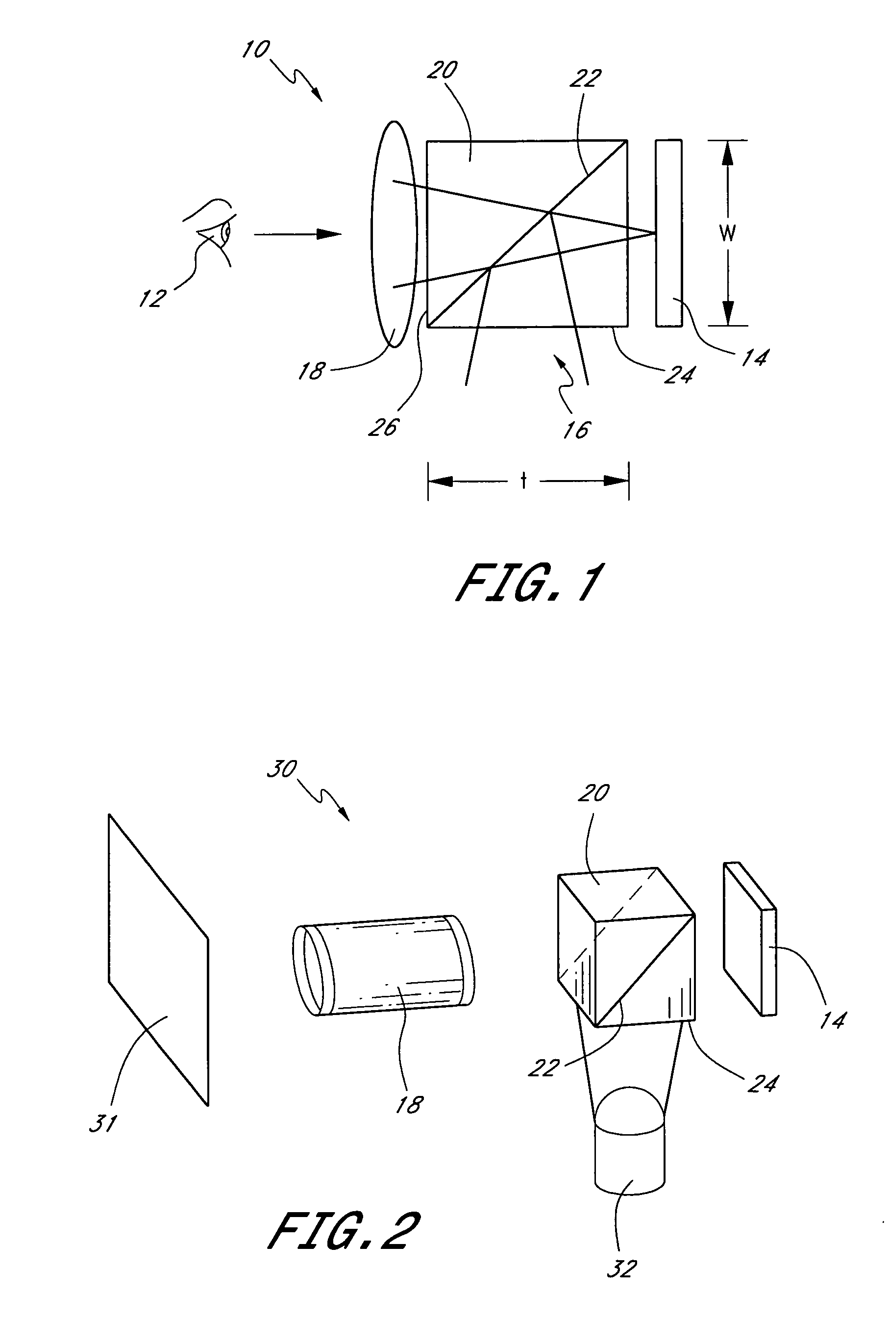
To present graphics or other visual information to a viewer, images and / or symbols, e.g., text or numbers, can be projected onto a screen or directed into the viewer's eye. FIG. 1 schematically illustrates a display 10 disposed in front of a viewer 12 (represented by an eye). In a preferred embodiment, this display 10 includes a spatial light modulator 14 that is illuminated with light 16 and imaged with imaging or projection optics 18. The spatial light modulator 14 may comprise, for example, a reflective polarization modulator such as a reflective liquid crystal display. This liquid crystal spatial light modulator preferably comprises an array of liquid crystal cells each which can be individually activated by signals, e.g., analog or digital, to produce a high resolution pattern including characters and / or images. More generally, the spatial light modulator may comprise an array of modulators or pixels that can be selectively adjusted to modulate light. The projection optics 18 ...


PUM


Abstract

Various embodiments involving structures and methods for illumination can be employed, for example, in projectors, head-mounted displays, helmet-mounted displays, back projection TVs, flat panel displays as well as other optical systems. Certain embodiments may include prism elements for illuminating, for example, a spatial light modulator. Light may be coupled to the prism in some cases using fiber optics or lightpipes. The optical system may also include a diffuser having scatter features arranged to scatter light appropriately to produce a desired luminance profile. Other embodiments are possible as well.

Description

BACKGROUND OF THE INVENTION 1. Field of the Invention This invention relates to illumination devices and methods that may be used, for example, in displays and projection systems, etc. 2. Description of the Related Art Optical devices for presenting information and displaying images are ubiquitous. Some examples of such optical devices include computer screens, projectors, televisions, and the like. Front projectors are commonly used for presentations. Flat panel displays are employed for computers, television, and portable DVD players, and even to display photographs and artwork. Rear projection TVs are also increasingly popular in the home. Cell phones, digital cameras, personal assistants, and electronic games are other examples of hand-held devices that include displays. Heads-up displays where data is projected on, for example, a windshield of a automobile or in a cockpit of an aircraft, will be increasingly more common. Helmet mounted displays are also employed by the mili...

Claims


Application Information

Patent Timeline
IPC IPC(8): G02B27/10G02B27/14
CPCG02B27/0081
Inventor CASSARLY, WILLIAM J.MCGUIRE, JAMES P. JR.
Owner SYNOPSYS INC
Why Eureka
Eureka Blog
Learn More