Eureka AIR delivers breakthrough ideas for toughest innovation challenges, trusted by R&D personnel around the world.

OLED miniaturized display constant-brightness modulation method

A microdisplay, constant brightness technology, applied in static indicators, cathode ray tube indicators, instruments, etc., can solve the problems of OLED devices not being able to maintain a fixed brightness well, increasing the number of adjustments, and overmodulation.

Active Publication Date: 2016-10-12
YUNNAN NORTH OLIGHTEK OPTO ELECTRONICS TECH
View PDF6 Cites 11 Cited by
  • Summary
  • Abstract
  • Description
  • Claims
  • Application Information

AI Technical Summary

Problems solved by technology

When the difference between the current brightness and the fixed brightness is relatively large in this modulation method, the number of adjustments will increase significantly, and the efficiency is not high; and when the brightness difference is small, if the modulation step value is too large, it will cause excessive modulation. As a result, the brightness of the OLED device cannot maintain a fixed brightness well.

Method used


Image

  • OLED miniaturized display constant-brightness modulation method
  • OLED miniaturized display constant-brightness modulation method
  • OLED miniaturized display constant-brightness modulation method

Examples


Embodiment 1

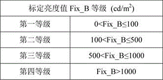
[0020] Example 1: (1) The OLED microdisplay needs to be at 100 cd / m 2 Work under the brightness of 100 cd / m 2 . Because 0

[0021] (2) The measured current brightness value Cur_B is 103 cd / m 2 , then the difference between the measured current luminance value and the calibrated luminance value B_degree=103-100=3 cd / m 2 ;

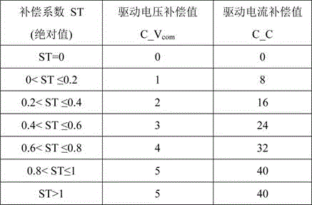
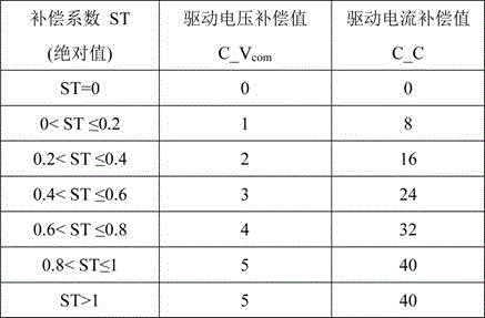
[0022] (3) Calculate the compensation coefficient ST=(Cur_B-Fix_B) / Dif_B=3 / 5=0.6;

[0023] (4) According to ST=0.6, the corresponding driving voltage compensation value C_V com is 3;

[0024] (5) Modulate with the current driving voltage value plus the compensation value, and finally realize the brightness of the OLED microdisplay to work at 100 cd / m 2 Down.

Embodiment 2

[0025] Example 2: (1) The OLED microdisplay needs to be at 1100 cd / m 2 Work under the brightness of 1100 cd / m 2 . Because 500

[0026] (2) The measured current brightness value Cur_B is 918 cd / m 2 , then the difference between the measured current luminance value and the calibrated luminance value B_degree=918-1100= -182 cd / m 2 ;

[0027] (3) Calculate the compensation coefficient ST=(Cur_B-Fix_B) / Dif_B= -182 / 15= -12.13;

[0028] (4) According to︱ST︱=12.13 and the difference between the current brightness value and the calibration brightness value is a negative value, the corresponding driving voltage compensation value C_V com is -5;

[0029] (5) Modulate with the current driving voltage value plus the compensation value, and finally realize the brightness of the OLED microdisplay to work at 100 cd / m 2 Down.


PUM


Abstract

The invention relates to the technical field of display brightness control of an OLED miniaturized display and specifically relates to an OLED miniaturized display constant-brightness modulation method. According to the invention, a compensation coefficient is determined through actual measurement of a difference between a current brightness value and a calibrated brightness value, driving current compensation or driving voltage compensation is carried out through the compensation coefficient, and thus the purpose of maintaining constant brightens of the OLED miniaturized display is realized. According to the invention, modulation stepping is automatically adjusted according to the difference between current brightness and fixed brightness in a modulation process so that the phenomenon of excessive modulation caused by too frequent modulation or mismatch between the modulations stepping and the brightness difference in a conventional modulation mode is avoided.

Description

technical field [0001] The invention belongs to the technical field of display brightness control of OLED microdisplays, in particular to a constant brightness modulation method of OLED microdisplays. Background technique [0002] OLED is an organic electroluminescent diode, which is an emerging display technology that has developed rapidly in recent years. It has a series of characteristics such as simple panel and simple process, and has the potential of low cost. It can meet the requirements of higher performance and larger information capacity of display technology in today's information technology era, and has become one of the hottest topics in the scientific and industrial circles. . Generally speaking, the diagonal of the display screen is less than 1 inch, which is called OLED microdisplay. [0003] OLED microdisplays can be widely used in various fields. Different occasions have different brightness requirements, but generally OLED microdisplays are required to m...

Claims


Application Information

Patent Timeline
IPC IPC(8): G09G3/3208G09G5/10
CPCG09G3/3208G09G5/10
Inventor 朱胜迪段瑜杨俊彦曹坤宇吴斌
Owner YUNNAN NORTH OLIGHTEK OPTO ELECTRONICS TECH
Why Eureka
Eureka Blog
Learn More