Liquid crystal display apparatus

a liquid crystal display and apparatus technology, applied in the field of display apparatus, can solve the problems of decreasing the luminance of the fluorescent lamps themselves, and achieve the effects of enhancing the luminance of the displayed image, suppressing the heat-liberation of the light source, and improving blur

Inactive Publication Date: 2006-09-26
HITACHI DISPLAYS +1
View PDF32 Cites 86 Cited by
  • Summary
  • Abstract
  • Description
  • Claims
  • Application Information

AI Technical Summary

Benefits of technology

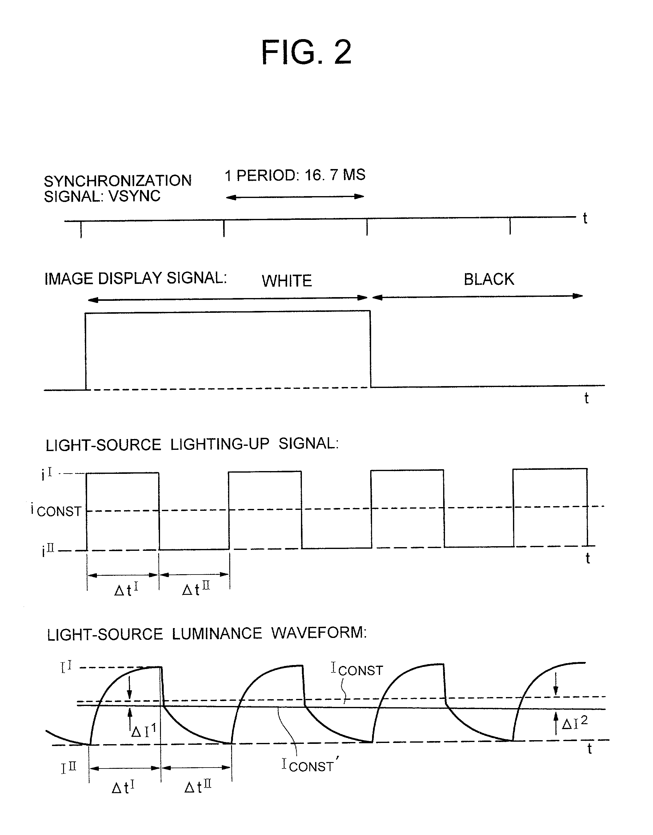
[0010]This setting, in the former case (i.e., the image that is bright as a whole), feeds to the light-source the lamp current that is higher than the reference current, thereby resulting in a temperature increase in the light-source which is larger by the amount of feeding the higher lamp current. In the case of the fluorescent lamps, the temperature increase raises the mercury (Hg) vapor pressures inside the fluorescent lamps, thereby increasing the number of mercury atoms (i.e., mercury vapor quantity) inside the fluorescent lamps. Meanwhile, if there exist surplus mercury atoms inside the fluorescent lamps, the surplus mercury atoms heighten a probability that ultraviolet rays generated inside the fluorescent lamps by the collision between the mercury atoms and the electrons are absorbed into the mercury atoms, eventually decreasing the luminances of the fluorescent lamps themselves. In order to avoid this influence, after having set the lamp current to be higher than the above-described reference current during the above-described time-period, the lamp current is restored back to the reference current before the mercury vapor pressures inside the fluorescent lamps are altered. Changing the lamp current in this way makes the luminances of the fluorescent lamps higher than those of the fluorescent lamps at the time when the reference current is fed thereto. Also, in the latter case (i.e., the image that is dark as a whole), if the luminance of the light-source is high, it becomes required to suppress a slight leakage of the light from a pixel displaying black or a color close thereto. On the screen that is dark as a whole, even in a pixel the light-transmittance of which is set to be the highest within the screen, the absolute quantity of the light to be transmitted is small. On account of this, the lamp current is set to be lower than the reference current, thereby suppressing the luminance of the light-source so as to throttle the leakage of the light from the pixel displaying black or the color close thereto, and at the same time reducing the power consumption in the light-source.
[0021]Here, the 1st light-emission luminance is higher than the 2nd light-emission luminance. As one example thereof, the time ratio of the 1st light-emission luminance during the period is set to be 60% or smaller when the display data is of motion-frame pictures, and is set to be 60% or larger when the display data is of freeze-frame pictures. Also, the 2nd light-emission luminance is set to be substantially 0, which is intended to enhance the reproducibility at the time when the afterimage and the luminance of the 2nd light-emission luminance are low.

Problems solved by technology

Meanwhile, if there exist surplus mercury atoms inside the fluorescent lamps, the surplus mercury atoms heighten a probability that ultraviolet rays generated inside the fluorescent lamps by the collision between the mercury atoms and the electrons are absorbed into the mercury atoms, eventually decreasing the luminances of the fluorescent lamps themselves.

Method used


Image

  • Liquid crystal display apparatus
  • Liquid crystal display apparatus
  • Liquid crystal display apparatus

Examples


Embodiment Construction

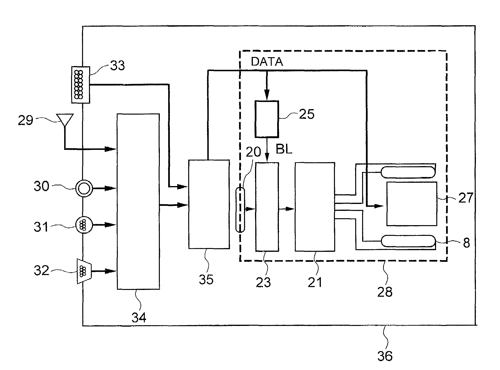
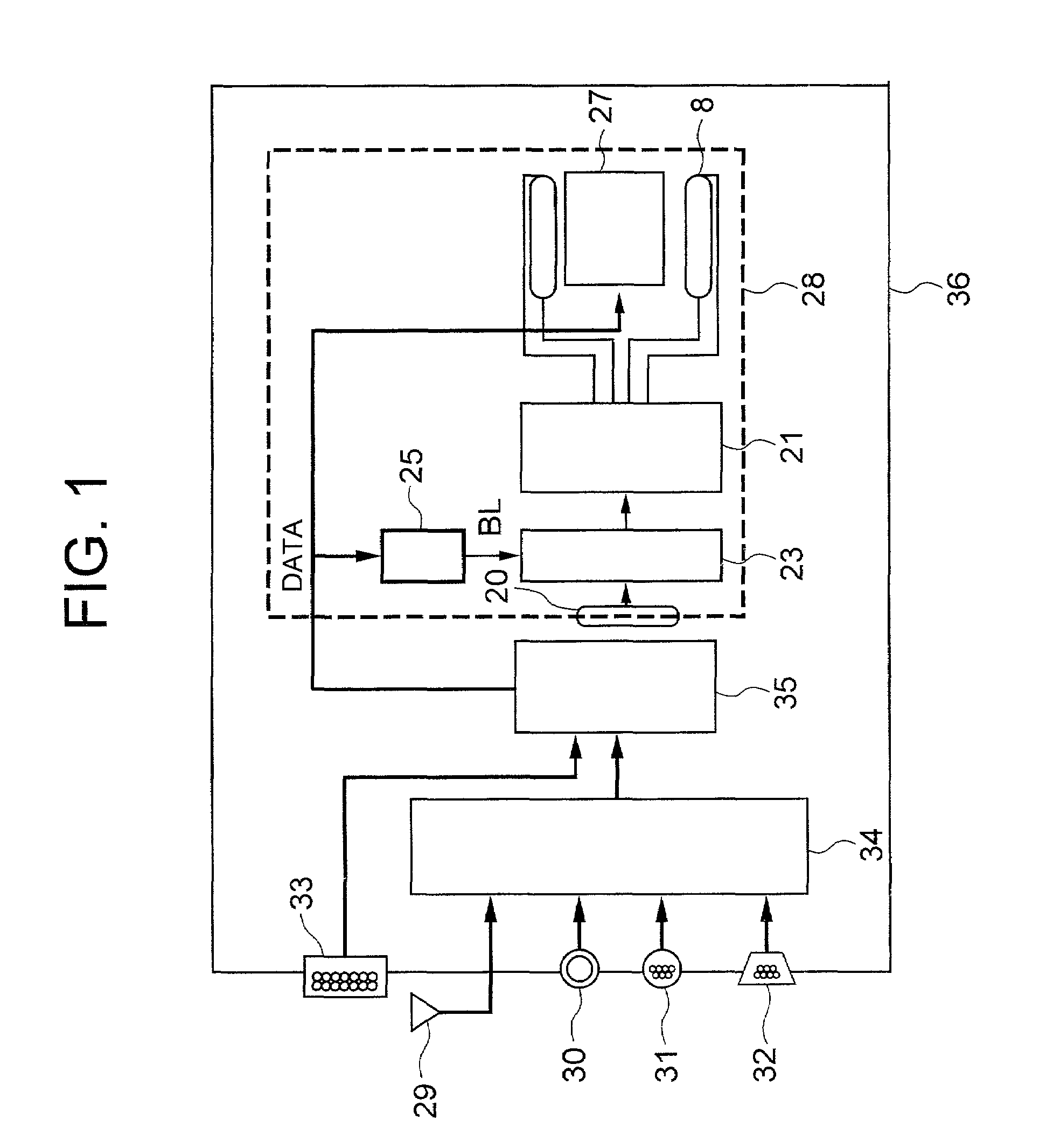
[0082]The present invention includes a panel on which a plurality of pixels are located, a light-source for visualizing an image displayed on the plurality of pixels, and a controlling circuit for controlling the light-source. Here, during a 1st time-period, the controlling circuit feeds the light-source an electric current having a 1st intensity. During a 2nd time-period, the controlling circuit feeds the light-source an electric current having a 2nd intensity (which differs from the 1st intensity). Also, the controlling circuit repeats the 1st time-period and the 2nd time-period periodically. Furthermore, the controlling circuit controls the light-source so that the intensity of a light emitted from the light-source in this period (i.e., an integrated value obtained by integrating the luminance of the light during this period) will become higher than an integrated value of the luminance in the case where the light-source is lit up by a rating electric current during the same time-...


PUM

PropertyMeasurementUnit
display luminanceaaaaaaaaaa
thicknessaaaaaaaaaa
electric currentaaaaaaaaaa

Abstract

The present invention includes a panel on which a plurality of pixels are located, a light-source for visualizing an image displayed on the plurality of pixels, a controlling circuit for controlling the light-source, and an image-signal tone characteristic controlling circuit. Moreover, the light-source controlling circuit has a function of repeating a period. Here, the period includes a 1st time-period during which an electric current having a 1st intensity is fed to the light-source, and a 2nd time-period during which an electric current having a 2nd intensity differing from the 1st intensity is fed to the light-source. The light-source controlling circuit controls the 1st time-period and the 2nd time-period in accordance with display information. Also, in accordance with the display information as well, the tone characteristic controlling circuit is controlled so that the excellent contrast will be always available.

Description

BACKGROUND OF THE INVENTION[0001]1. Field of the Invention[0002]The present invention relates to a display apparatus using a liquid crystal display device, an electroluminescence device, or the like. More particularly, it relates to a display apparatus having a light-source that is suitable for enhancing the luminance of the display screen with a high-efficiency and for making the luminance uniform on the display screen.[0003]2. Description of the Related Art[0004]The display apparatus, which uses the liquid crystal display device (which is also referred to as “liquid crystal display panel”), the electroluminescence device (which, depending on a fluorescent material used, is classified into an organic-family and an inorganic-family and, hereinafter, is referred to as “EL device”), a field emission device (which, hereinafter, is referred to as “FE device”), or the like, performs the image display. However, unlike the case of a Braun tube (which, hereinafter, is referred to as “CRT”, ...

Claims


Application Information

Patent Timeline
Patent Type & Authority Patents(United States)
IPC IPC(8): G09G3/36G02F1/1335G02F1/133G02F1/13357G09F9/00G09G3/20G09G3/34
CPCG09G3/342G09G3/3648G02F1/133604G09G2360/16G09G3/2011G09G3/2018G09G3/2077G09G2310/024G09G2310/08G09G2320/0252G09G2320/0257G09G2320/0261G09G2320/062G09G2320/0633G09G2320/064G09G2320/0673G09G2320/103G09G2340/16G02F2001/133612G02F1/133612G02F1/133
Inventor NITTA, HIROYUKIMAEDA, TAKESHIKAWABE, KAZUYOSHIHIRAKATA, JUNICHI
Owner HITACHI DISPLAYS
Why Eureka
Try Eureka