
Ink jet recording head and ink jet recording apparatus

a recording head and ink jet technology, applied in the field of ink jet recording head, can solve the problems of reducing recording quality and worsening problem, and achieve the effect of high image quality recording and uneven recording

Inactive Publication Date: 2008-06-19
CANON KK
View PDF11 Cites 35 Cited by
  • Summary
  • Abstract
  • Description
  • Claims
  • Application Information

AI Technical Summary

Benefits of technology

[0014]Accordingly, the present invention is achieved in view of the above point, and an object thereof is to provide an ink jet recording head and an ink jet recording apparatus wherein a white line caused by a head tilt and a recording unevenness can be prevented from occurring and a high image quality recording can be realized.
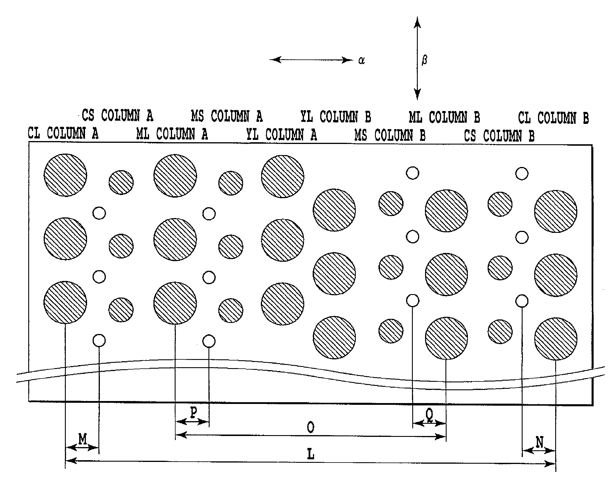
[0016]According to the present invention, a white line and a recording unevenness are not caused and a high image quality recording result can be obtained, when nozzles are configured such that the centers of nozzles with different ejection amounts are not allocated on a line in the main scanning direction in a recording head provided with nozzles ejecting three types of droplets, large, medium and small in an ejection amount.

Problems solved by technology

An outstanding granularity in a recording output reduces a recording quality thereof.
This phenomenon is apparent in a case where a diameter of a small nozzle is as small as one third of that of a large nozzle and a nozzle pitch is large, and a recording unevenness with a particular period, caused by a periodical change of a recording head tilt during scanning, further worsens the problem.

Method used


Image

  • Ink jet recording head and ink jet recording apparatus
  • Ink jet recording head and ink jet recording apparatus
  • Ink jet recording head and ink jet recording apparatus

Examples


first embodiment

[0036]Hereinafter, a first embodiment of the present invention will be described in detail in reference to the drawings.

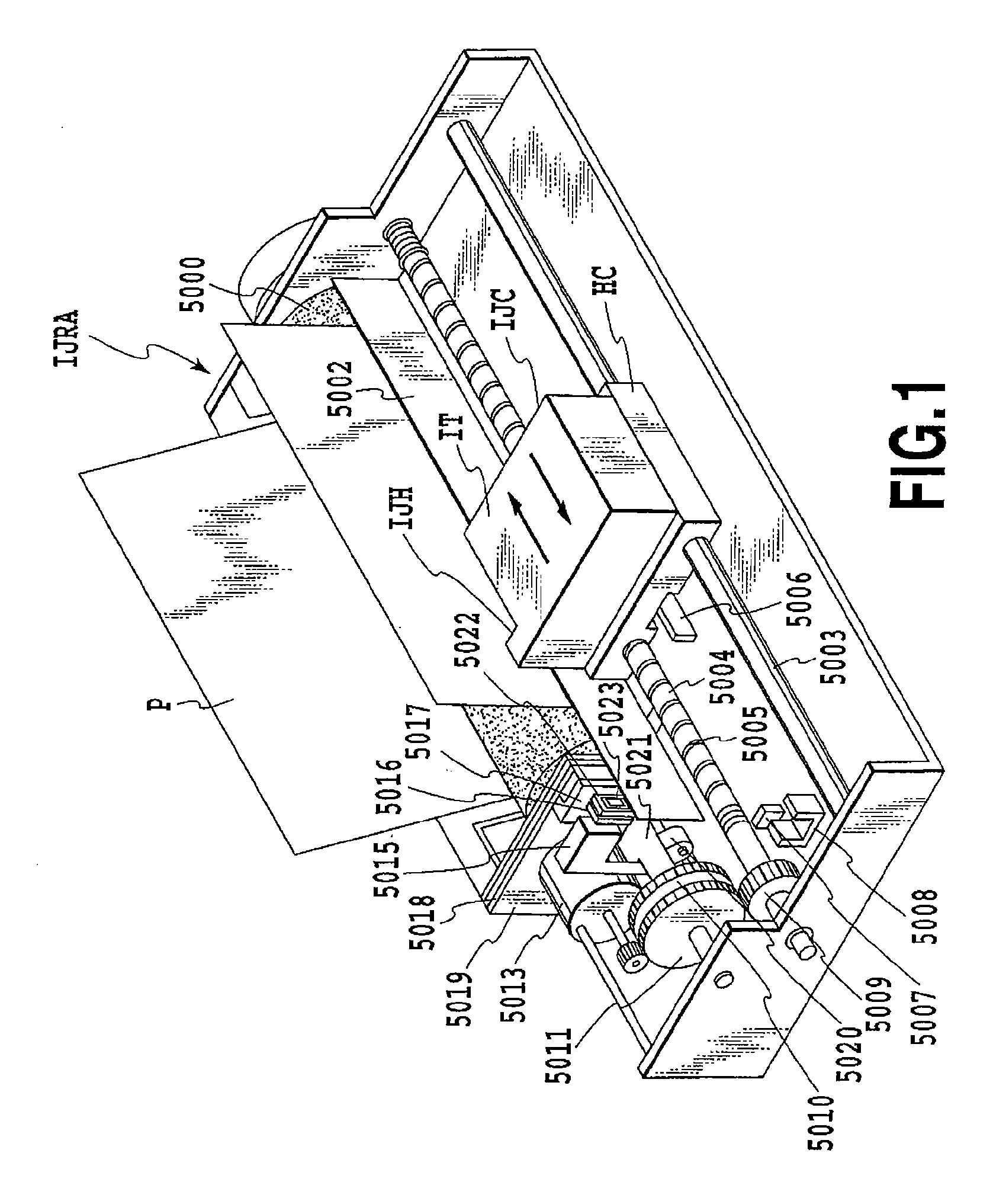
[0037]FIG. 1 is a perspective appearance view showing a configuration of an ink jet recording apparatus IJRA according to an embodiment of the present invention. In FIG. 1, a carriage HC, engaged with a spiral groove 5004 of a lead screw 5005 rotating via driving force transmission gears 5009 to 5011 for transmitting rotation of a driving motor 5013, has a pin (not shown in the drawing) and is supported by a guide rail 5003 to reciprocate in directions of arrows a and b. An integrated inkjet cartridge IJC incorporating a recording head IJH and an ink tank IT is mounted on the carriage HC. Also, a main supporting board 5018 of the ink jet recording apparatus IJRA supports a paper pressing board 5002 for pressing a recording media P against a platen 5000 across a moving direction of the carriage HC. Further, the main supporting board 5018 supports photo-couplers 5007...

second embodiment

[0057]FIG. 7 is a diagram showing an arrangement of each nozzle, enlarged for easy understanding, in a recording head according to the present embodiment. A configuration is similar to that of the recording head shown in FIG. 5, and includes a heater, an element substrate, a flow path forming substrate, a nozzle, a separation wall, an ejector, etc. However, a point different from the first embodiment is that nozzles ejecting a small droplet and medium droplet are not arranged in a staggered manner. A small nozzle ejecting a small droplet and a medium nozzle ejecting a medium droplet are arranged on a line alternately like nozzle columns 12 and 13 in the drawing. A pitch r2 of small nozzles and medium nozzles is 21.2 μm, approximately a half of a pitch r1 (42.3 μm) of large nozzles arranged in a nozzle column 11 and nozzle column 14. Also, the nozzle pitch r2 of small nozzles in the nozzle column 12 is shifted against the nozzle pitch r1 in the nozzle column 11, and an offset amount ...


PUM


Abstract

An ink jet recording head and an ink jet recording apparatus are provided to prevent occurrence of a white line or recording unevenness due to a head tilt, and realize a high image quality recording. For this purpose, in a recording head provided with nozzles ejecting three types of droplets, a large droplet, medium droplet and small droplet, nozzles are configured such that any nozzles are not arranged on the same line at the centers thereof in the main scanning direction.

Description

BACKGROUND OF THE INVENTION[0001]1. Field of the Invention[0002]The present invention relates to an ink jet recording head for recording by ejecting ink to a recording medium.[0003]2. Description of the Related Art[0004]Recently, a number of recording apparatuses have been used, and high speed, high resolution, high image quality, low noise, etc are required for these recording apparatuses. Recording apparatuses which meet these requirements include an ink-jet type recording apparatus (hereinafter, referred to as ink jet recording apparatus). An ink jet recording apparatus is configured to eject ink (recording liquid) droplets from recording head ejectors, and to perform recording by letting these ink droplets adhere to a recording medium. In this ink jet recording apparatus, since recording is performed by means of ink ejection from a recording head, recording can be performed without any contact to a recording medium to realize an extremely stable recording image.[0005]FIG. 8 is a...

Claims


Application Information

Patent Timeline
Patent Type & Authority Applications(United States)
IPC IPC(8): B41J2/14
CPCB41J2/1404B41J2/145B41J2202/11B41J2002/14475B41J2/2125
Inventor OIKAWA, MASAKIKANEKO, MINEOTSUCHII, KENYAMANE, TORUTOMIZAWA, KEIJIMATSUMOTO, MITSUHIROIDE, SHUICHITAKINO, KANSUINABESHIMA, NAOZUMI
Owner CANON KK
Learn More