
Stackable structural reactor

a structural reactor and stacking technology, applied in the direction of gas-gas reaction process, combustion using catalytic materials, combustion types, etc., can solve the problems of reducing the capacity of the reactor, not performing particularly well near the center of the reactor, and limiting the throughput that can be accommodated

Active Publication Date: 2008-06-19
JOHNSON MATTHEY PLC
View PDF18 Cites 30 Cited by
  • Summary
  • Abstract
  • Description
  • Claims
  • Application Information

AI Technical Summary

Benefits of technology

This patent describes how to install a new type of reactor called a MonoReactor™. The installation involves putting together two parts: an outer tube and a monolith made up of many small fins arranged like a ring. These fins create spaces where fluids can pass through the reactor. To make this work better, we first squeeze the monolith tightly around its original size (called the uncompressed state). Then, it's inserted into the outer tube while still being very tightly packed. Finally, we release the pressure on the monolith which allows it to fully expand back to its larger shape without losing any space between itself and the outer tube. Overall, this process makes sure that the MonoReactor works perfectly when it needs to be installed.

Problems solved by technology

The technical problem addressed by this patent is how to improve the efficiency and increase the throughput of reactors placed inside cylindrical tubes, while also preventing issues related to metallic creep and thermal expansion. Additionally, the patent describes various potential uses for the reactor including but not limited to traditional areas like catalytic fuel reforming and petroleum processing.

Method used


Image

  • Stackable structural reactor
  • Stackable structural reactor
  • Stackable structural reactor

Examples


Embodiment Construction

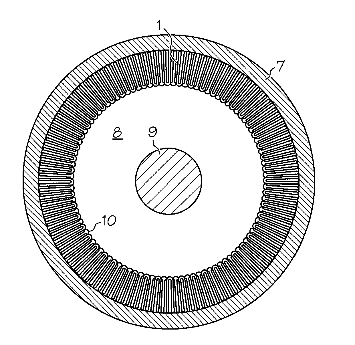
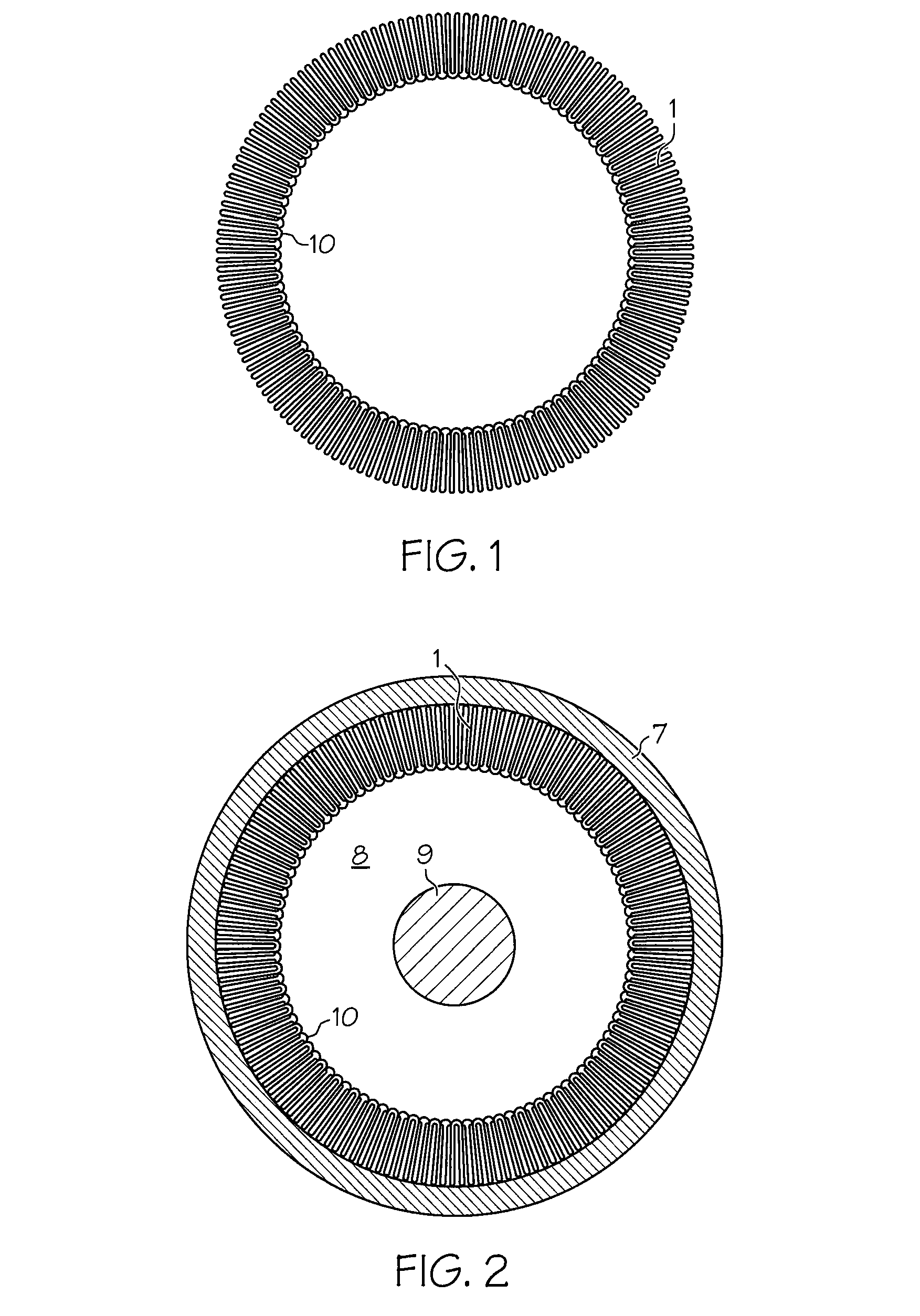
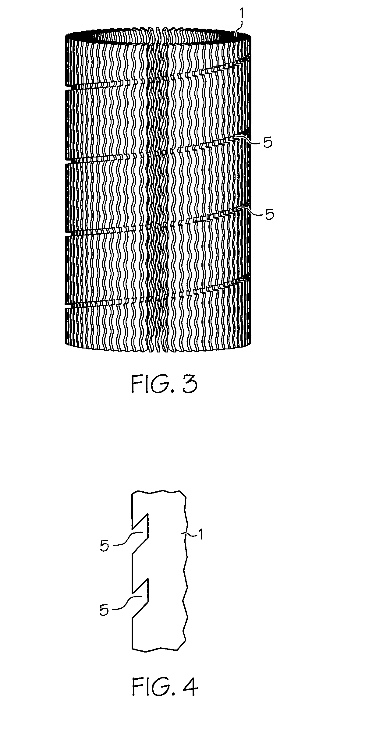
[0039]The reactor of the present invention, sometimes referred to as a stackable structural reactor (“SSR”), comprises a catalyst or reaction support, preferably made of metal foil, the metal foil comprising a plurality of leaves or fins which define a relatively large surface area for catalytic reaction and / or heat exchange. In a preferred embodiment, the fins are formed by folding metal foil back and forth upon itself to define a monolith. The terms “leaves” and “fins” are used interchangeably in this specification. If the monolith is used for catalytic reactions, its surfaces can be coated with a suitable catalyst. The fins can be formed around a center support such as a central mandrel, pipe, post, link piece or other structure in an annular arrangement in order to form a monolith of general annular cross section, as viewed in the direction of the flow of fluid through the reactor. The monolith and central structure can be inserted within a cylindrical tube or outer tube 7, such...


PUM

PropertyMeasurementUnit
Fractionaaaaaaaaaa
Fractionaaaaaaaaaa
Lengthaaaaaaaaaa

Abstract

A reactor including a monolith having a plurality of fins in an annular arrangement for receiving fluid flow through the reactor. The monolith is disposed within a generally cylindrical outer tube, and around a corrugated inner tube. The reactor includes a device for urging the monolith radially outward, so as to maintain contact between the monolith and the outer tube.

Description


Claims


Application Information

Patent Timeline
Owner JOHNSON MATTHEY PLC
Learn More