Suction device and supporting device having the same

Inactive Publication Date: 2008-06-26
DUAL MEMRISTOR LTD CO
View PDF10 Cites 5 Cited by
  • Summary
  • Abstract
  • Description
  • Claims
  • Application Information

AI Technical Summary

Problems solved by technology

In such a configuration, during operation, in addition to operation of the operating rod 13 using one hand of a user, it is required to support the conventional suction device 1 using the other hand of the user before the base 11 can be placed to abut against the peripheral portion 122 of the sucking member 12, thereby resulting in inconvenience during use.

Method used


Image

  • Suction device and supporting device having the same
  • Suction device and supporting device having the same
  • Suction device and supporting device having the same

Examples


Embodiment Construction

[0033]Before the present invention is described in greater detail, it should be noted that like elements are denoted by the same reference numerals throughout the disclosure.

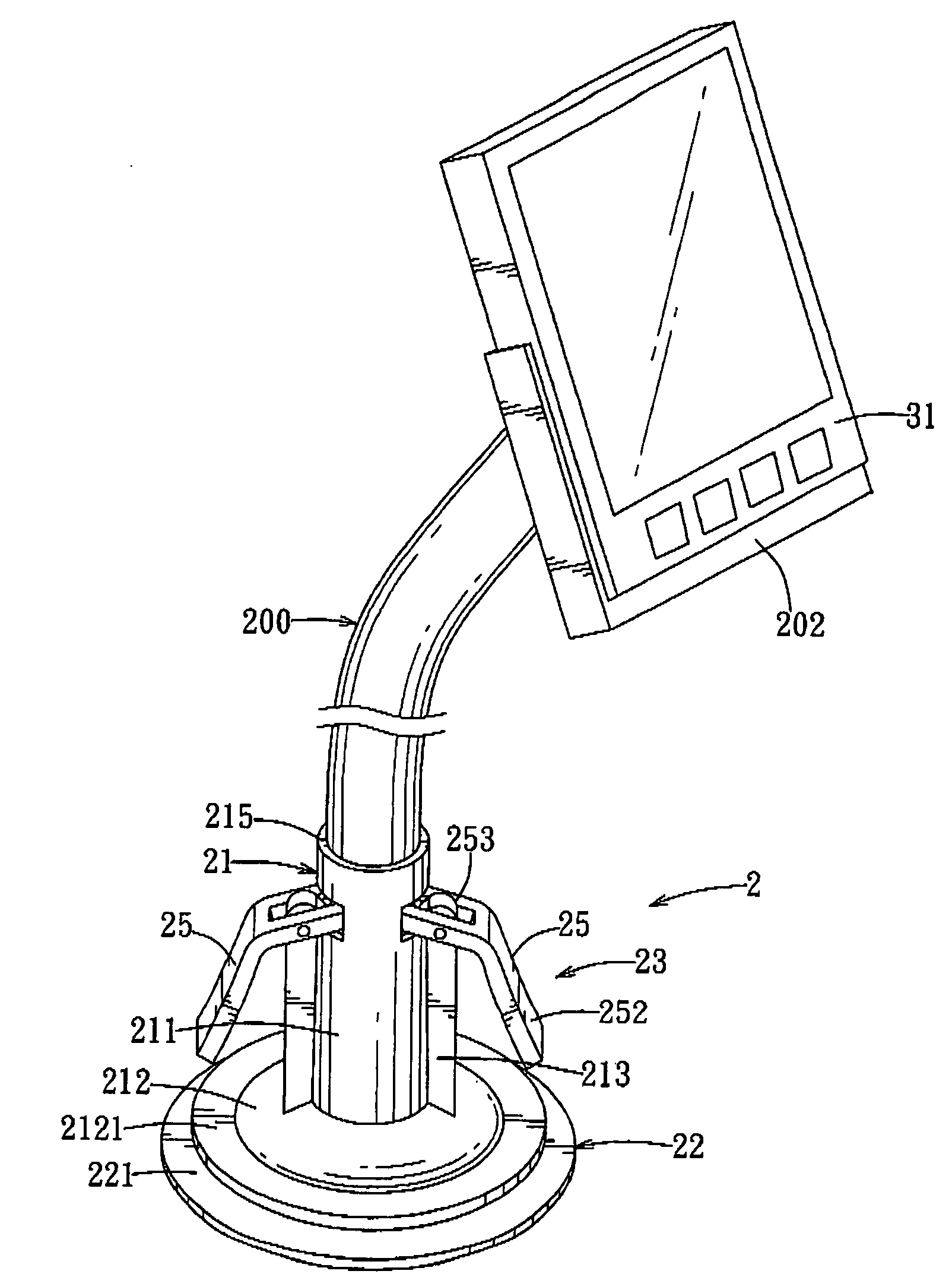
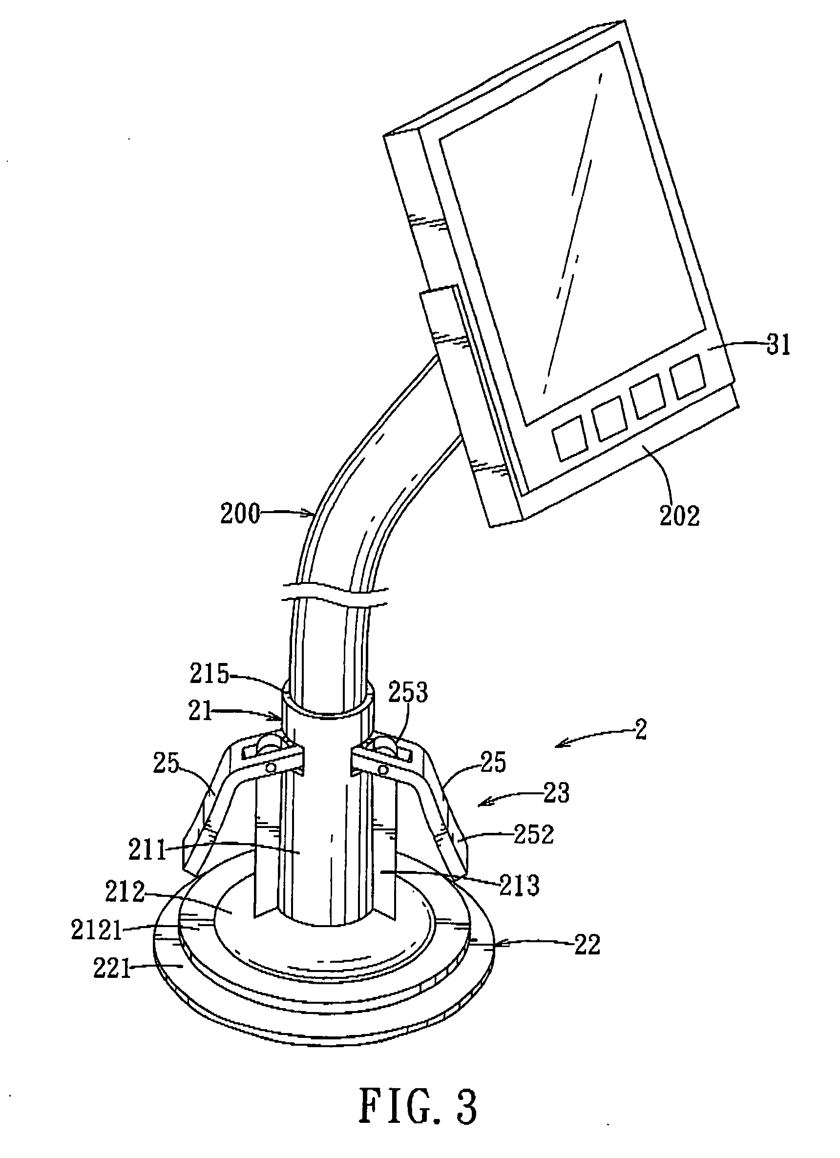
[0034]Referring to FIGS. 3 to 5, the first preferred embodiment of a suction device 2 according to the present invention is shown to include an upright sleeve 21, a sucking member 22, a connecting member 24, and an operating rod unit 23.

[0035]The sleeve 21 is made of a hard plastic material, extends along a longitudinal direction (A), and has an open top end 215, an open bottom end 216, and a lower end portion 212 having a diameter that increases gradually toward the bottom end 216 (see FIG. 5). The sleeve 21 further has an annular flange 2121 that extends radially and outwardly from the bottom end 216. The sleeve 21 has an annular outer surface 211 formed with a through hole unit that is disposed adjacent to the top end 215, and a pivot block unit that is disposed adjacent to the through hole unit. In this embo...


PUM


Abstract

A suction device includes a sucking member having a connecting body connected integrally to a flexible disc body that is disposed under an upright sleeve, a connecting member disposed in the sleeve and connected to the connecting body, and an operating rod connected pivotally to a pivot block unit on the sleeve and to the connecting member The operating rod is operable so that an assembly of the connecting member and the connecting body is pulled upwardly, thereby forming a vacant space between a central portion of the disc body and a supporting surface to which a peripheral portion of the disc body is attached sealingly.

Description

CROSS-REFERENCE TO RELATED APPLICATION[0001]This application claims priority of Taiwanese Application No. 095222648, filed on Dec. 22, 2006.BACKGROUND OF THE INVENTION[0002]1. Field of the Invention[0003]The invention relates to a suction device, more particularly to a suction device that can be operated using a single hand, and a supporting device having the same.[0004]2. Description of the Related Art[0005]Referring to FIGS. 1 and 2, a conventional suction device 1 is shown to include a hollow base 11 having a sleeve 14 that extends upwardly from a top surface 111 of the base 11, a sucking member 12 disposed under the base 11, a connecting rod 121 extending upwardly from a top surface of the sucking member 12 through the base 11, and an operating rod 13. The operating rod 13 has a pivot end portion 133 connected pivotally to the connecting rod 121, an operating end portion 132 opposite to the pivot end portion 133, and an intermediate fulcrum portion 131. The pivot end portion 133...

Claims


Application Information

Patent Timeline
IPC IPC(8): F16M13/02A44B1/18
CPCB60R11/00F16B47/00B60R2011/0056B60R11/02
Inventor WANG, CHEN-HSINGSU, CHIA-HUNG
Owner DUAL MEMRISTOR LTD CO
Why Eureka
Try Eureka