Flower shears

a technology for flower shears and shears, applied in the field of flower shears, can solve the problems of decreased cutting range of flower shears under this condition, and laborious operation of flower shears

Inactive Publication Date: 2008-07-03
LIN THOMAS
View PDF13 Cites 29 Cited by
  • Summary
  • Abstract
  • Description
  • Claims
  • Application Information

AI Technical Summary

Benefits of technology

[0007]To achieve this objective of the present invention, the flower shears comprises a stationary unit, a movable unit and a driving unit. The stationary unit is provided with a first blade portion at an upper part thereof, a first transmission portion at a middle part thereof, and a first handle at a lower part thereof. The movable unit has a middle part pivotally connected to the stationary unit, and an upper part defining a second blade portion. The driving unit is pivotally connected to a bottom end of the movable unit and provided with a second handle at a lower part thereof and a second transmission portion at a top end ther

Problems solved by technology

On the premise that the pivotal angle between the two blades is fixed, the cutting range of the flower shears will increase if the length of the cutting edge is longer than the length of the handle, but the flower shears is laborious in operation under this condition.
On the contrary, the flower shears will be laborsaving in operation if the length of the cutting edge is short

Method used


Image

  • Flower shears
  • Flower shears
  • Flower shears

Examples


Embodiment Construction

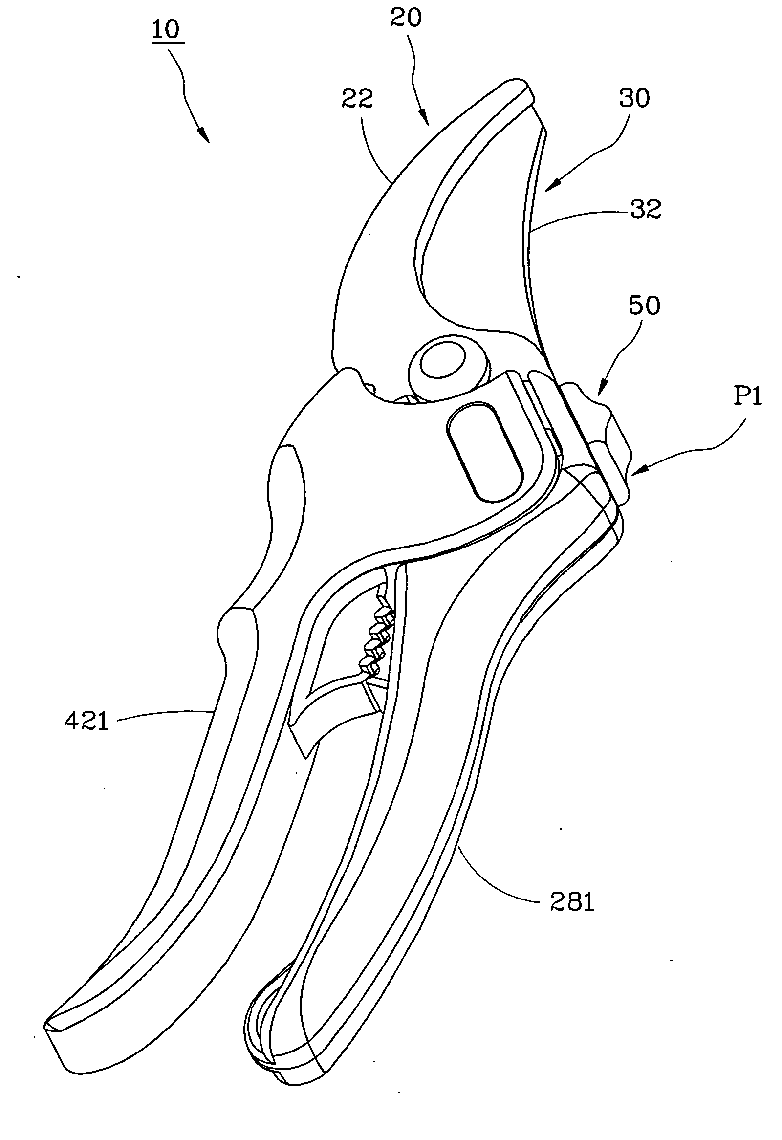
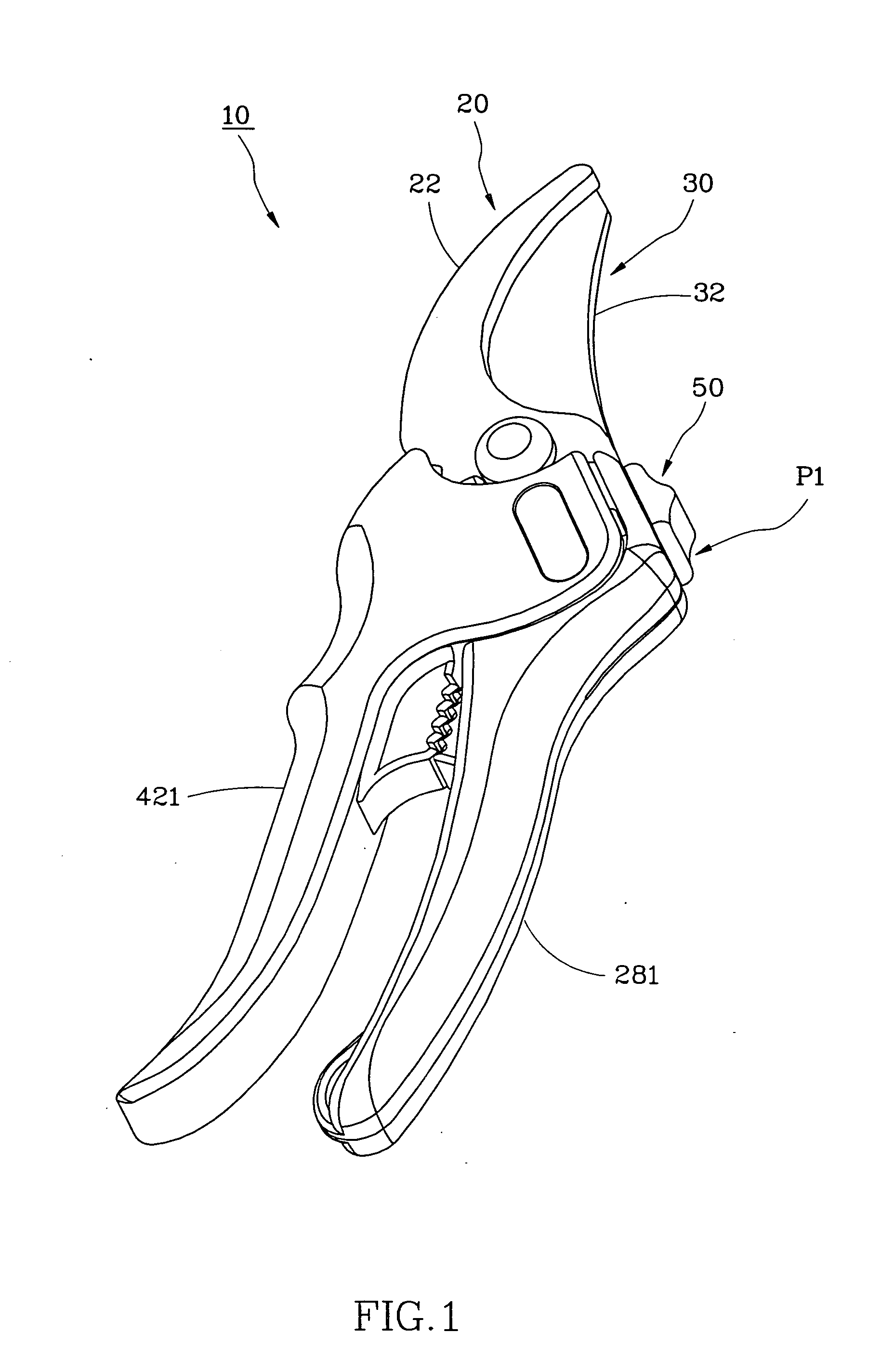
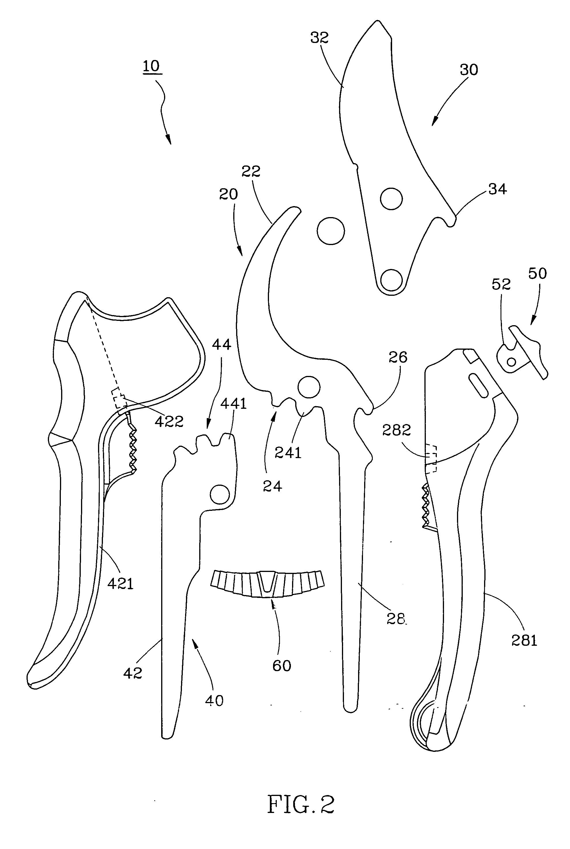
[0015]As shown in FIG. 1 and FIG. 2 a flower shears 10 in accordance with a preferred embodiment of the present invention comprises a stationary unit 20, a movable unit 30, a driving unit 40, a limiter 50 and a spring member 60.

[0016]The stationary unit 20 is provided with a first blade portion 28 at an upper part thereof, a transmission portion 24 at one lateral side of a middle part thereof, a first stop portion 26 at the other lateral side of the middle part thereof, and a first handle 28 at a lower part thereof. The transmission portion 24 has teeth 241 and the stationary unit 20 is covered at the middle and lower parts thereof with a sheath 281 for holding by a user. The sheath 281 is provided with a protrusion 282 located close to a middle part thereof.

[0017]The movable unit 30 is pivotally connected at a middle part thereof to the stationary unit 20 and provided with a second blade portion 32 at an upper part thereof and a second stop portion 34 at one lateral side of the low...


PUM


Abstract

A flower shears includes a stationary unit, a movable unit and a driving unit. The stationary unit has a first blade portion at an upper part thereof, a first transmission portion with teeth at a middle part thereof, and a first handle at a lower part thereof. The movable unit is pivotally connected at a middle part thereof to the stationary unit and provided at an upper part thereof with a second blade portion. The driving unit is pivotally connected to a bottom end of the movable unit and provided with a second handle at a lower part thereof and a second transmission portion with teeth meshed with the teeth of the first transmission portion, such that the second blade portion of the moveable unit can be driven by the second handle through the engagement of the teeth of the first and second transmission portions to pivotally move toward the first blade portion of the stationary unit for cutting things.

Description

BACKGROUND OF THE INVENTION[0001]1. Field of the Invention[0002]The present invention relates generally to a gardening implement and more specifically, to a flower shears that is laborsaving in operation.[0003]2. Description of the Related Art[0004]A conventional flower shears comprises two blades pivotally fastened to each other. The blades are respectively provided with a cutting edge and a handle. On the premise that the pivotal angle between the two blades is fixed, the cutting range of the flower shears will increase if the length of the cutting edge is longer than the length of the handle, but the flower shears is laborious in operation under this condition. On the contrary, the flower shears will be laborsaving in operation if the length of the cutting edge is shorter than the length of the handle; however, the cutting range of the flower shears under this condition will decrease.[0005]Another conventional flower shears is provided with a spring member fastened between the tw...

Claims


Application Information

Patent Timeline
IPC IPC(8): B26B13/00
CPCA01G3/02
Inventor LIN, THOMAS
Owner LIN THOMAS
Why Eureka
Try Eureka