Riser card module
- Summary
- Abstract
- Description
- Claims
- Application Information
AI Technical Summary
Problems solved by technology
Method used
Image

Examples
first embodiment
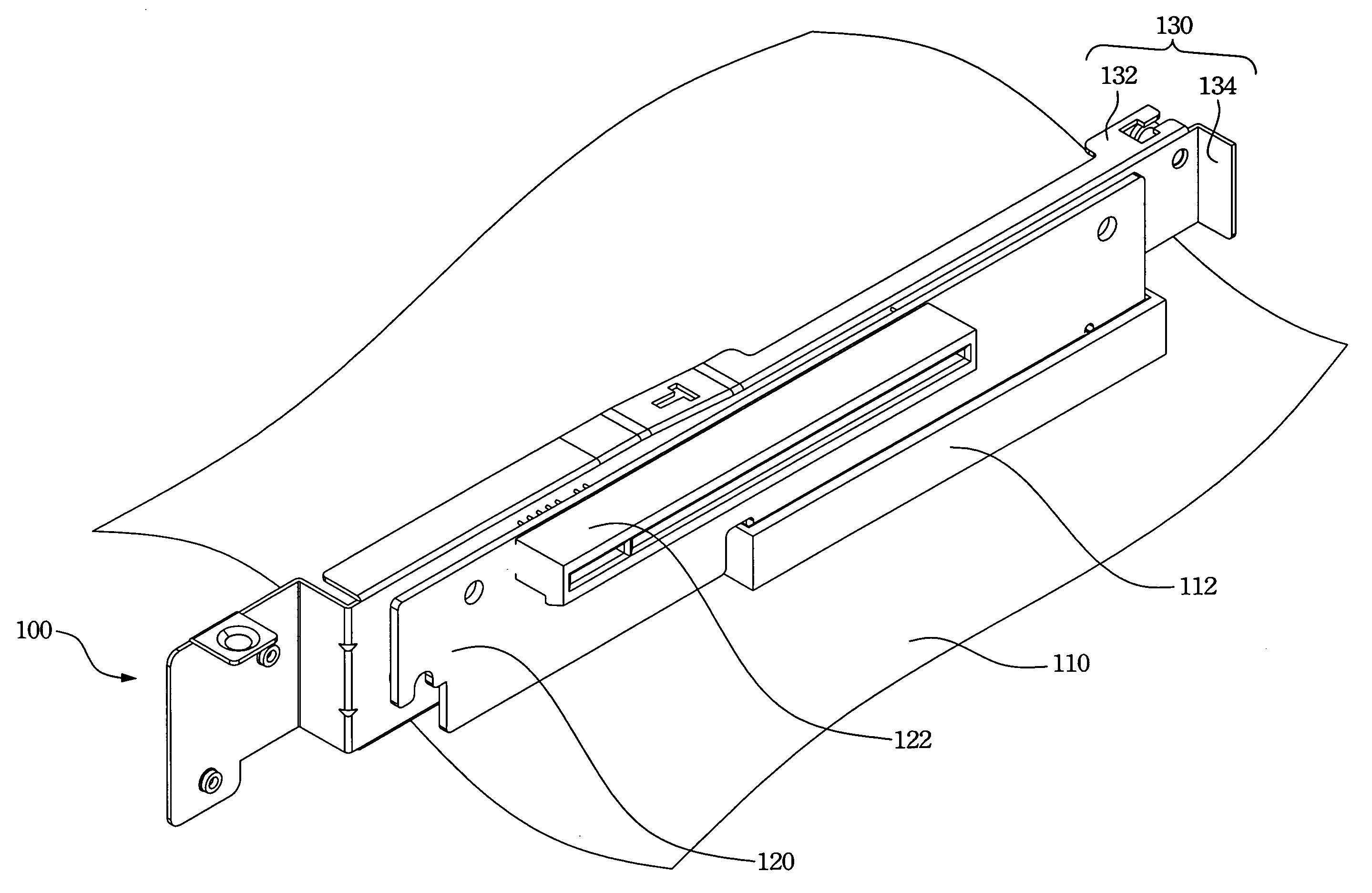
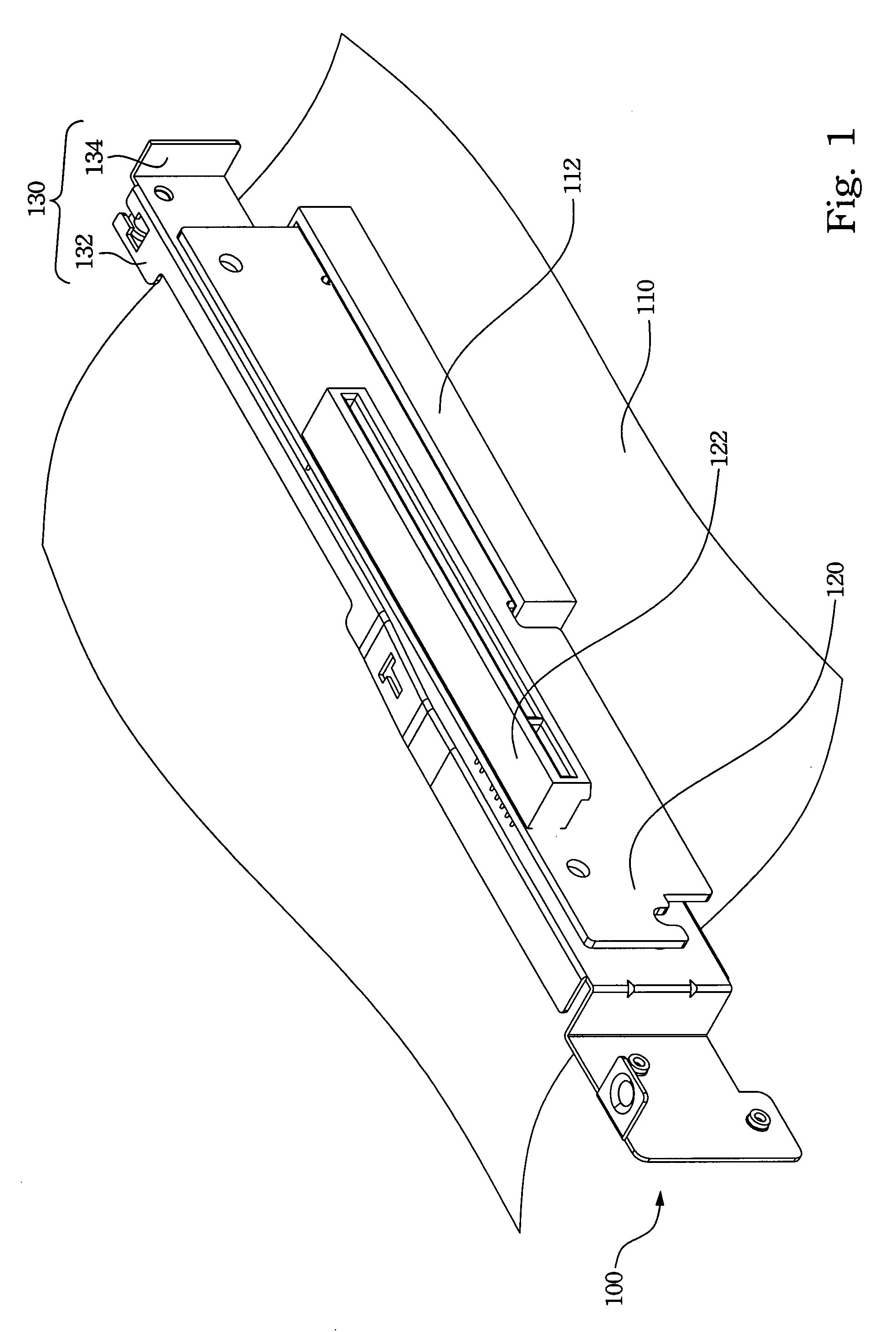
[0020]Please refer to FIG. 1. This figure depicts the riser card module 100 of the first embodiment installed on the main board 110. The riser card module 100 is installed on the slot 112 of the main board 110. The riser card module 100 includes a riser card 120 and a mounting rack 130. The riser card 120 is inserted in the slot 112 vertically. Moreover, the riser card 120 includes a expansion slot 112 for installing a expansion card (not showing in the figure) then the expansion card could install on the main board in parallel.
[0021]The mounting rack 130 includes an upright board 134 mounting the riser card in parallel. The mounting rack 130 further includes a top board 132 vertically connected to the side of the upright board 134 opposite to the main board 110.
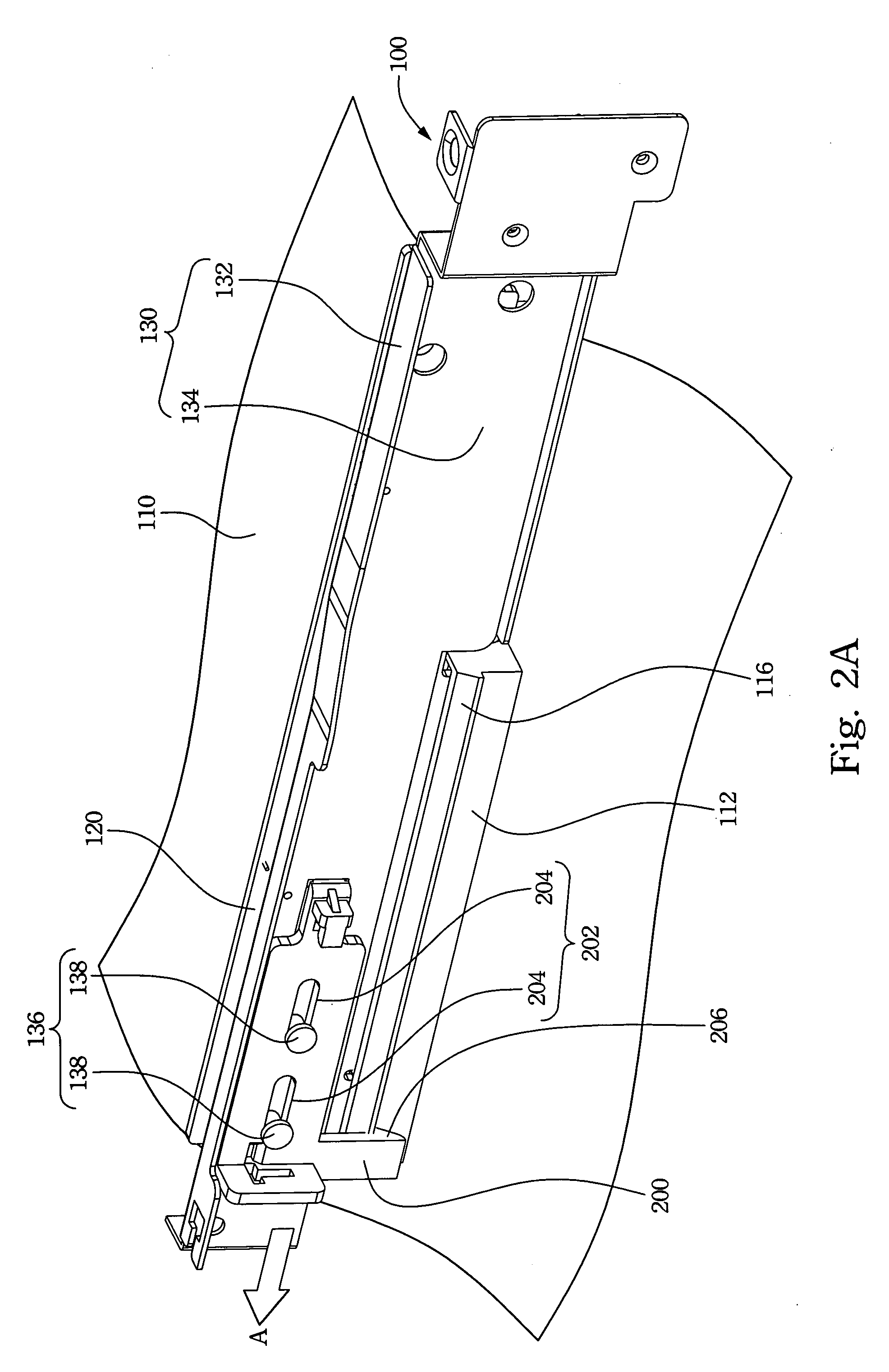
[0022]In order to describe the operation in detail, please refer to FIG. 2A and FIG. 2B together. FIG. 2A depicts the riser card module 100 of the first embodiment at another view angle. FIG. 2B depicts the sliding device 20...
second embodiment
[0025]In order to dismount the riser card module more easily, a flexible force member is arranged in this embodiment. Please refer to FIG. 3. This figure depicts the second embodiment. The flexible force member 302 is arranged on the mounting rack 130. one side of the flexible force member 302 is connected to the top board 132, the other side of the flexible force member is connected to the sliding device 200.
[0026]When the flexible force member 302 is pulled towards the direction of arrow B, the flexible force member 302 can tow the sliding device 200 toward the direction of arrow C so that the second hook member 206 is disengaged from the first hook member 116. When the hook member 206 and 116 are not hooked together, the force toward arrow B can dismount the riser card 120 from the slot 112.
[0027]The upright board further includes a protrusion 304. The flexible force member 302 is looped around the protrusion 304 and connected to the sliding device 200. Hence, the protrusion 304 ...
third embodiment
[0031]The design of the elements described above has varied formation. For example, the third embodiment is a different design of the first sliding member and the second sliding member. Please refer to FIG. 4. FIG. 4 depicts the third embodiment.
[0032]In other embodiments described above, the first sliding member and the seconding member are two guide pillars and two guide openings. Therefore, the sliding stability of the sliding device is increased. In third embodiment, the first sliding member 402 is a guide pillar, and the second sliding member 404 is a guide opening. Hence, the number of the guide pillar and guide opening can be reduced. Moreover, the cost of the riser card module can be reduced when the sliding stability is acceptable.
[0033]Accordingly, the riser card module has the hook member arranged on the sliding device. Hence, the stability of the riser card module is increased. Moreover, the riser card module includes the flexible force member to tow the sliding device. ...
PUM
 Abstract
Description
Claims
Application Information
 - R&D Engineer
- R&D Manager
- IP Professional
- Industry Leading Data Capabilities
- Powerful AI technology
- Patent DNA Extraction
Browse by: Latest US Patents, China's latest patents, Technical Efficacy Thesaurus, Application Domain, Technology Topic.
© 2024 PatSnap. All rights reserved.Legal|Privacy policy|Modern Slavery Act Transparency Statement|Sitemap