

Vacuum IG window unit with metal member in hermetic edge seal
a vacuum ig window unit and metal member technology, applied in the field of vacuum ig units, can solve the problems of vacuum ig window units with metal members in hermetic edge seals, disadvantages in certain situations, and tend to be much flexing of vacuum ig window units
- Summary
- Abstract
- Description
- Claims
- Application Information
AI Technical Summary
Benefits of technology
Problems solved by technology
Method used
Image

Examples
Embodiment Construction
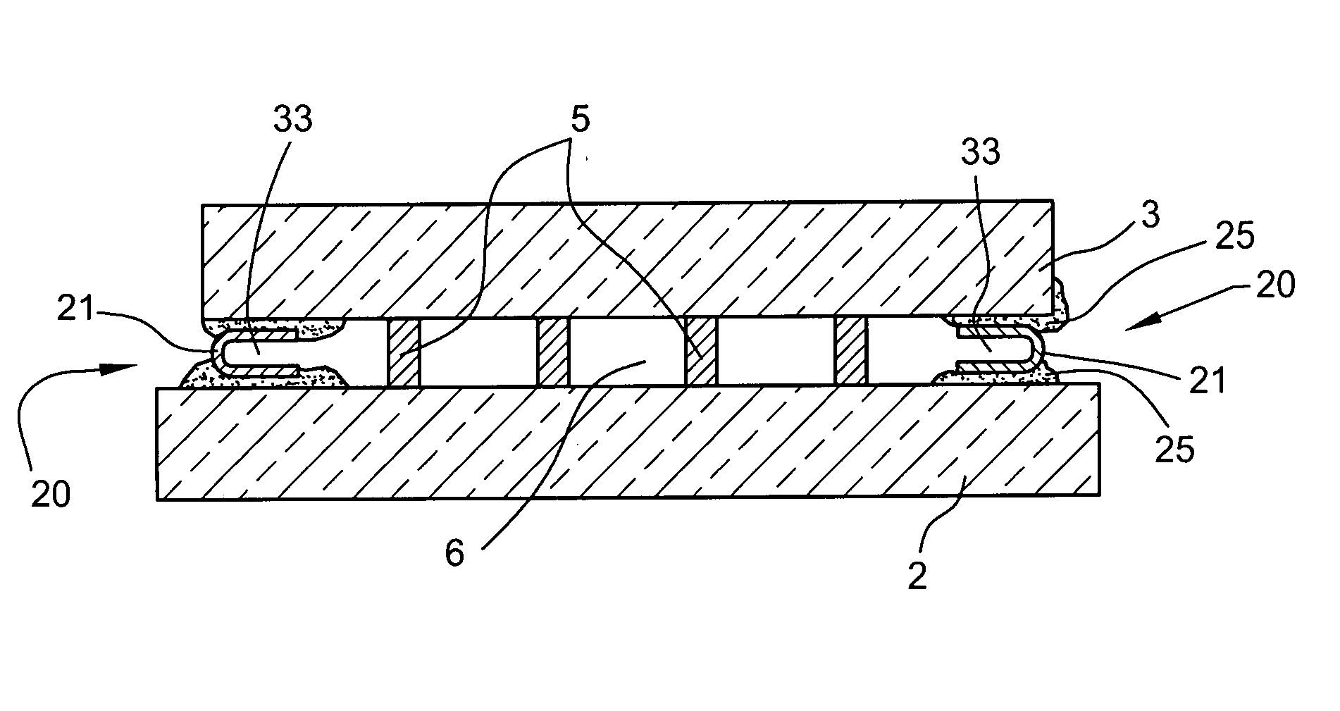
[0009]In certain example embodiments of this invention, there is provided a vacuum IG window unit including at least one metal member in an edge seal thereof, and / or a method of making the same.
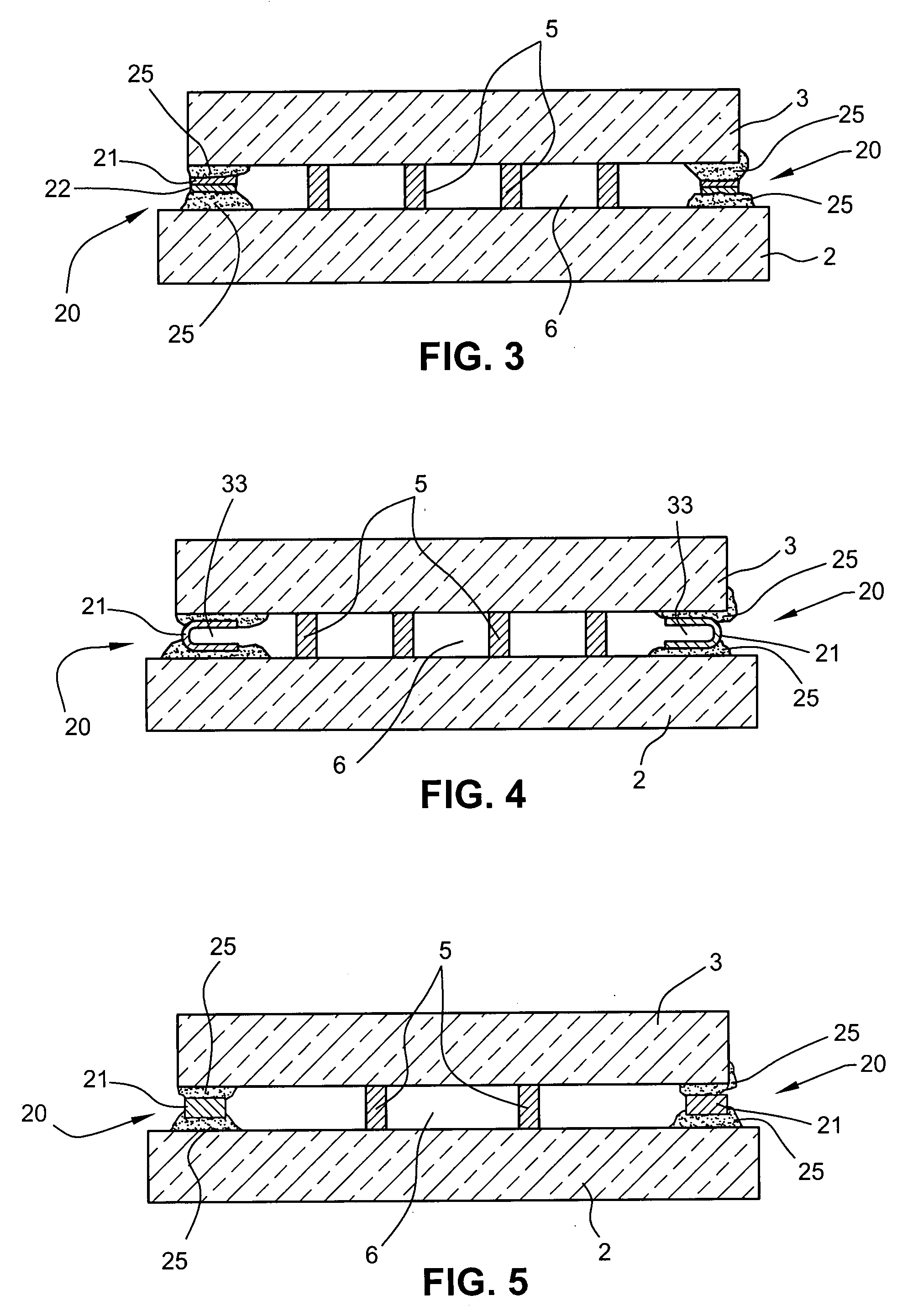
[0010]In certain example embodiments, the edge seal includes at least one metal member located between the opposing substrates (e.g., glass substrates). In certain example embodiments, the metal member need not directly contact the glass substrates. In certain example embodiments, the at least one metal member is bonded to the glass substrate(s) via a bonding material such as solder glass, frit and / or the like. Moreover, in certain example embodiments the metal member may have a coefficient of expansion similar to that of the glass substrates, with or without coated surface(s). In certain example embodiments, the provision of the at least one metal member in the edge seal, between the glass substrates, is advantageous in that this provides for a more flexible edge seal permitting more give an...
PUM
| Property | Measurement | Unit |
|---|---|---|
| transparent | aaaaa | aaaaa |
| transparent | aaaaa | aaaaa |
| transparent | aaaaa | aaaaa |
Abstract
Description
Claims
Application Information