
Vacuum IG window unit with metal member in hermetic edge seal

a vacuum ig window unit and metal member technology, applied in the field of vacuum ig units, can solve the problems of vacuum ig window units with metal members in hermetic edge seals, disadvantages in certain situations, and tend to be much flexing of vacuum ig window units

Active Publication Date: 2011-04-05
GUARDIAN GLASS LLC
View PDF22 Cites 27 Cited by
  • Summary
  • Abstract
  • Description
  • Claims
  • Application Information

AI Technical Summary

Benefits of technology

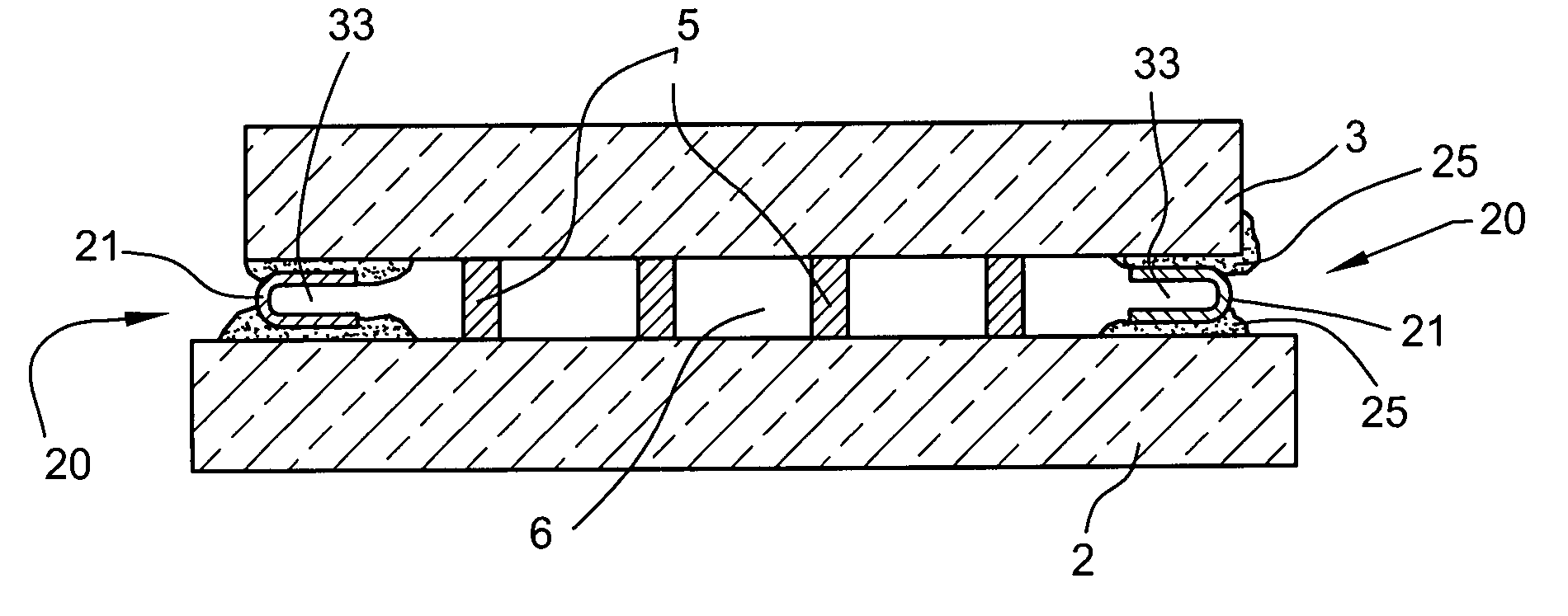
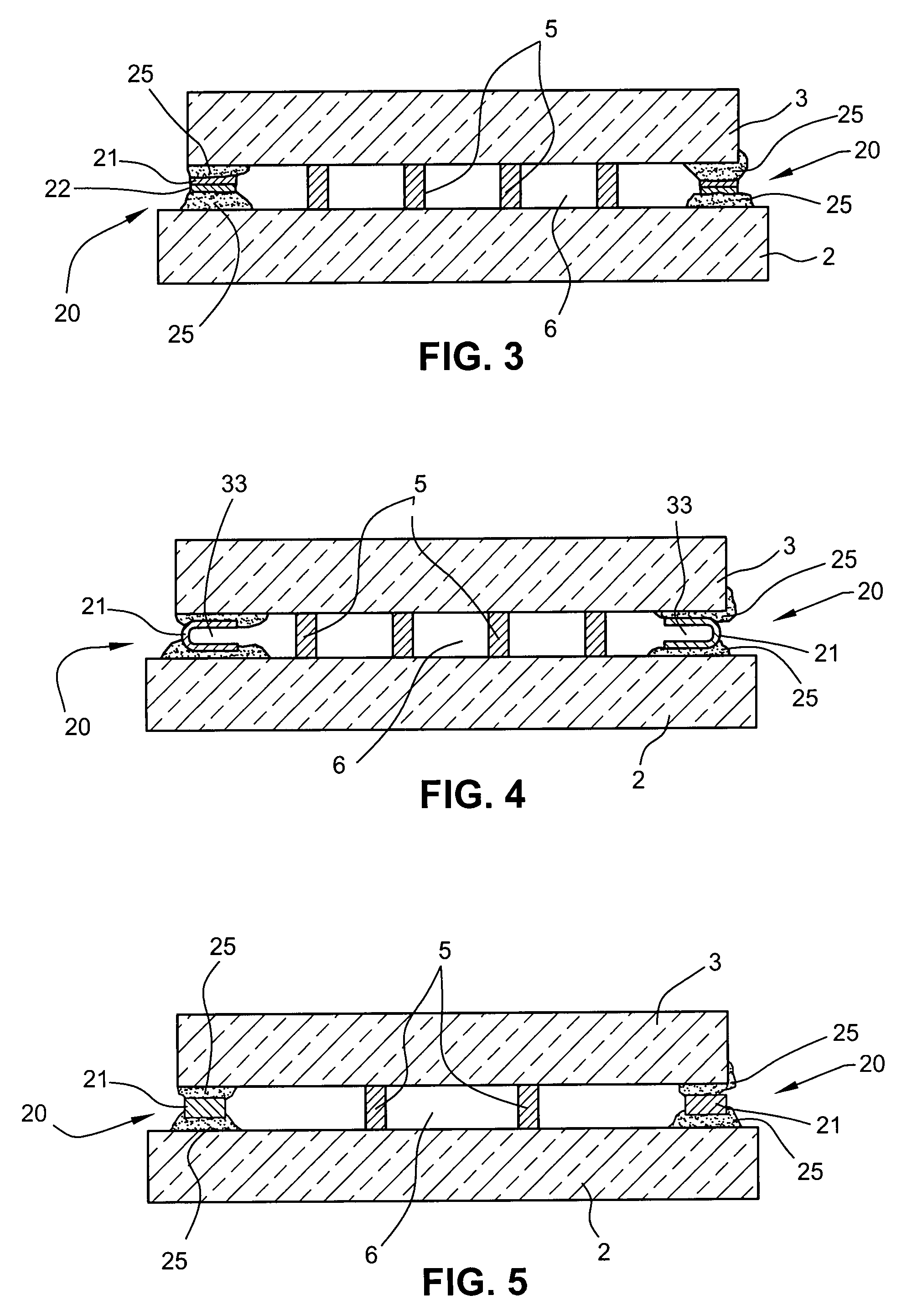
[0010]In certain example embodiments, the edge seal includes at least one metal member located between the opposing substrates (e.g., glass substrates). In certain example embodiments, the metal member need not directly contact the glass substrates. In certain example embodiments, the at least one metal member is bonded to the glass substrate(s) via a bonding material such as solder glass, frit and / or the like. Moreover, in certain example embodiments the metal member may have a coefficient of expansion similar to that of the glass substrates, with or without coated surface(s). In certain example embodiments, the provision of the at least one metal member in the edge seal, between the glass substrates, is advantageous in that this provides for a more flexible edge seal permitting more give and take during window flexing in different environmental conditions. The additional flexibility of the edge seal can reduce the amount of optical distortion caused by flexing of the window, and may also reduce the likelihood of window breakage in certain environmental conditions.

Problems solved by technology

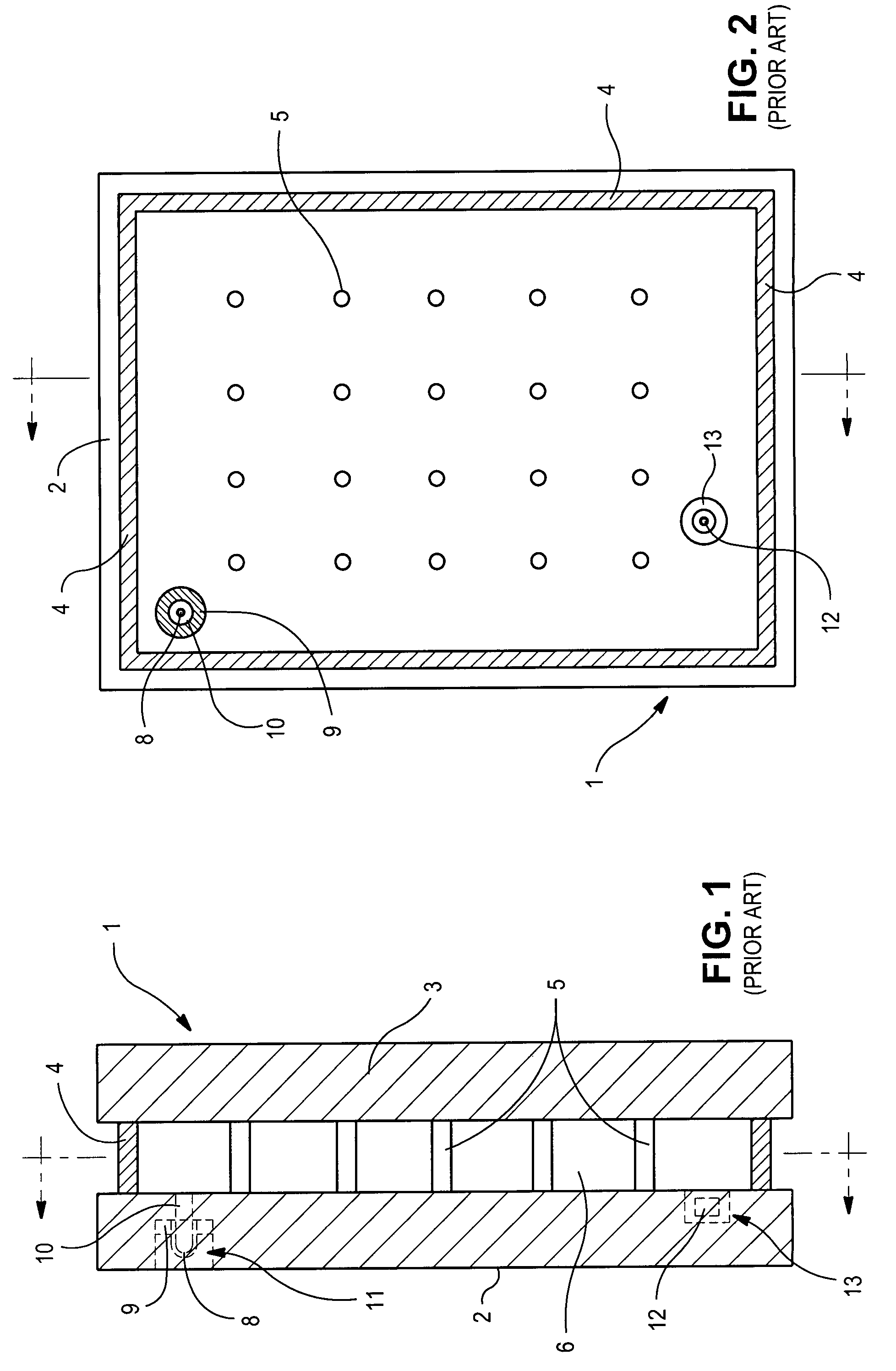
Unfortunately, the edge seal 4 of FIGS. 1-2, made entirely of solder glass and directly contacting both glass substrates, is disadvantageous in certain situations.
During many environmental conditions in which the VIG unit may be used (e.g., during hot, cold, and / or windy conditions), there tends to be much flexing of the vacuum IG window unit.

Method used


Image

  • Vacuum IG window unit with metal member in hermetic edge seal
  • Vacuum IG window unit with metal member in hermetic edge seal
  • Vacuum IG window unit with metal member in hermetic edge seal

Examples


Embodiment Construction

[0009]In certain example embodiments of this invention, there is provided a vacuum IG window unit including at least one metal member in an edge seal thereof, and / or a method of making the same.

[0010]In certain example embodiments, the edge seal includes at least one metal member located between the opposing substrates (e.g., glass substrates). In certain example embodiments, the metal member need not directly contact the glass substrates. In certain example embodiments, the at least one metal member is bonded to the glass substrate(s) via a bonding material such as solder glass, frit and / or the like. Moreover, in certain example embodiments the metal member may have a coefficient of expansion similar to that of the glass substrates, with or without coated surface(s). In certain example embodiments, the provision of the at least one metal member in the edge seal, between the glass substrates, is advantageous in that this provides for a more flexible edge seal permitting more give an...


PUM

PropertyMeasurementUnit
pressureaaaaaaaaaa
pressureaaaaaaaaaa
transparentaaaaaaaaaa

Abstract

A vacuum insulating glass (IG) unit and / or a method of making the same is / are provided. In certain example embodiments, the edge seal includes at least one metal member located between the opposing substrates (e.g., glass substrates). The at least one metal member may be bonded to the glass substrate(s) via a bonding material such as solder glass, frit and / or the like. The provision of the at least one metal member in the edge seal, between and / or exterior the glass substrates, is advantageous in that this provides for a more flexible edge seal permitting more give and take during window flexing in different environmental conditions. The additional flexibility of the edge seal may reduce the amount of optical distortion caused by flexing of the window, and / or the likelihood of window breakage in certain environmental conditions.

Description

[0001]This invention relates to a vacuum insulating glass (IG) unit, and a method of making the same. More particularly, this invention relates to a vacuum IG unit including at least one metal member in an edge seal thereof.BACKGROUND OF THE INVENTION[0002]Vacuum IG (VIG) units are known in the art. For example, see U.S. Pat. Nos. 5,664,395, 5,657,607, 6,399,169, 6,641,689, 6,692,600 and 5,902,652, the disclosures of which are all hereby incorporated herein by reference.[0003]Prior art FIGS. 1-2 illustrate a conventional vacuum IG unit. IG unit 1 includes two spaced apart sheets of glass 2 and 3 which enclose an evacuated or low pressure space 6 therebetween. Glass sheets 2 and 3 are interconnected by peripheral or edge seal of fused solder glass 4 and an array of support pillars or spacers 5.[0004]Pump out tube 8 is sealed by solder glass 9 to an aperture or hole 10 which passes from an interior surface of glass sheet 2 to the bottom of recess 11. A vacuum is attached to tube 8 so ...

Claims


Application Information

Patent Timeline
Patent Type & Authority Patents(United States)
IPC IPC(8): E06B3/24E04C2/54
CPCE06B3/6612E06B3/66333E06B3/6621Y02B80/24E06B2003/66338Y02A30/249Y02B80/22
Inventor COOPER, DAVID J.
Owner GUARDIAN GLASS LLC
Learn More