Indexable insert drill and a center insert therefore

a technology of indexable inserts and center inserts, which is applied in the direction of cutting inserts, twist drills, manufacturing tools, etc., can solve the problems of weakened insert pockets, particularly serious difficulties, and increased material costs surrounding insert pockets, and achieve the effect of width and strength

Active Publication Date: 2008-07-31
SANDVIK INTELLECTUAL PROPERTY AB
View PDF7 Cites 32 Cited by
  • Summary
  • Abstract
  • Description
  • Claims
  • Application Information

AI Technical Summary

Benefits of technology

[0011]By forming, in accordance with the invention, obtuse-angled inclined intermediate surfaces in the extension of the two side support surfaces of the cutting insert, the insert is given a tapering shape at the two opposite short ends thereof. This means that the cutting insert can retain the desired width and strength in the most sensitive part thereof, viz. the intermediate part adjacent to the screw hole. In combination with a suitable inclination of the cutting insert in relation to the center axis of the drill body, this tapering end shape can be utilized to provide a center pocket that, on one hand, is sufficiently large to accommodate the wide intermediate section of the cutting insert, and on the other hand placed and formed in such a way that it does not require an unacceptable sacrifice of material in the drill body. In other words, the center pocket can be formed without detrimentally affecting the stiffness and the strength of the front end of the drill body.

Problems solved by technology

Indexable insert drills having large or medium-sized holing diameters give rise to delicate balancing as a consequence of the complicated character of the drilling operation in respect of, for instance, chip control, balance, chip removal capacity, and the fact that the speed of rotation in the different parts of the drill body decreases from a maximum value at the periphery toward zero in the center of the drill body.
However, the difficulties become particularly serious when indexable insert drills for small holes, i.e., holes having a small diameter, are to be produced.
In particular, if the cutting inserts could be made comparatively sturdy, this will be on the expense of the material that surrounds the insert pockets in the basic body, i.e., the latter would become weakened.
Conversely, a decreasing quantity of material (cemented carbide) in the cutting insert weakens the insert.
Moreover, in small indexable insert drills, there is a special limitation so far that the only way in which the individual cutting insert can be fixed in the appurtenant pocket is to secure the insert by a screw, which has to have the head thereof countersunk in the hole in the cutting insert.
In practice, the difficulties and limitations pointed out above have meant that previously known indexable insert drills of the type mentioned initially have not been possible to be made with diameters smaller than 12.7 mm.
In this connection, the lack of space in a thin drill body is most problematic for the center insert and the pocket thereof, but less for the peripheral cutting insert and the pocket thereof.
12 mm (or less), such a cutting insert would, however, become too weak, in particular in the thin portions that surround the screw hole.
However, this alternative cannot be realized in practice, because such a material reduction would jeopardize the stiffness and the strength of the front end of the drill body.
The last-mentioned alternative would be non-expedient even if the center pocket would be tilted in relation to the center axis, because then the protection border would become too thin or partly cut away.

Method used


Image

  • Indexable insert drill and a center insert therefore
  • Indexable insert drill and a center insert therefore
  • Indexable insert drill and a center insert therefore

Examples


Embodiment Construction

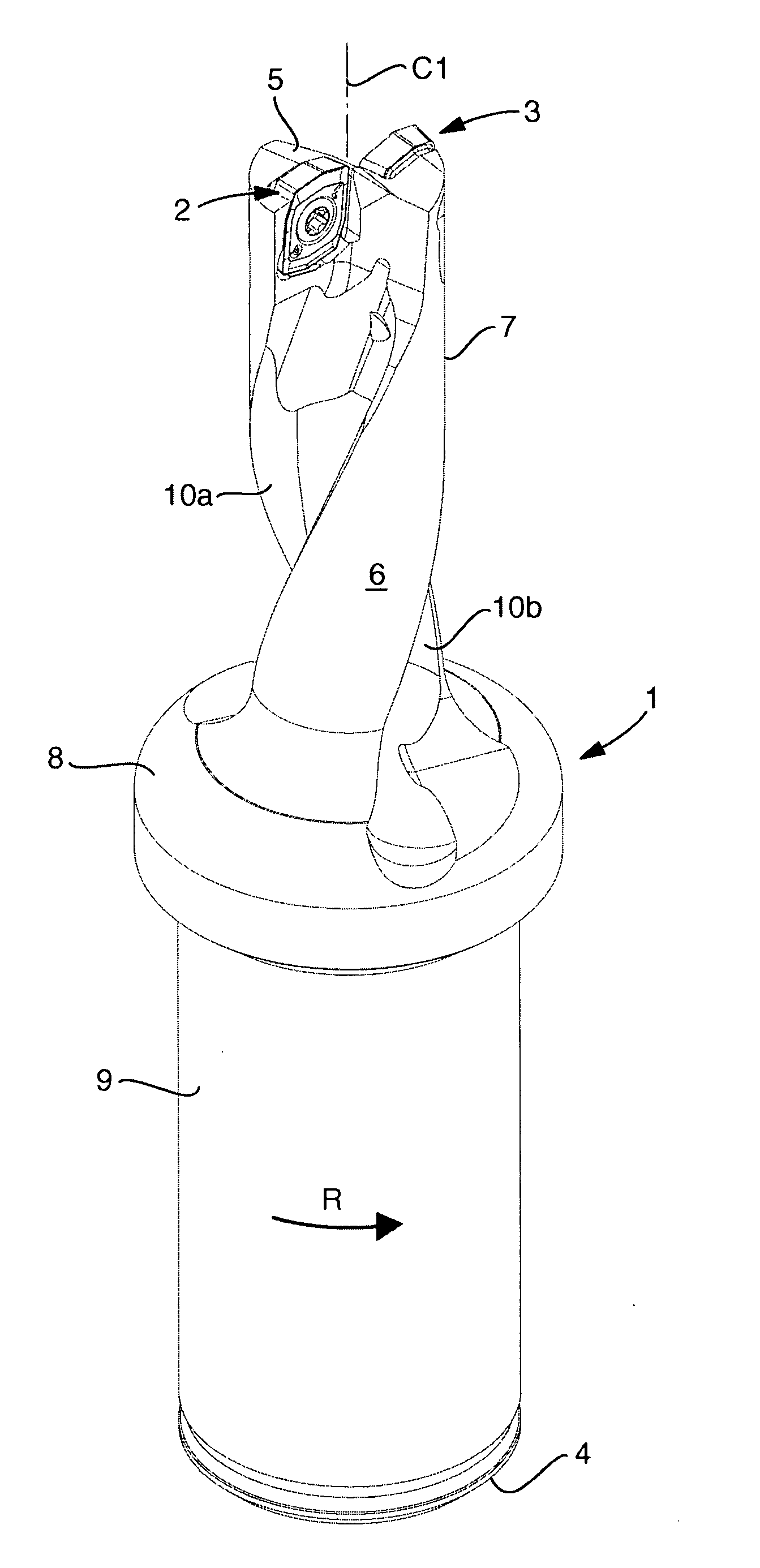
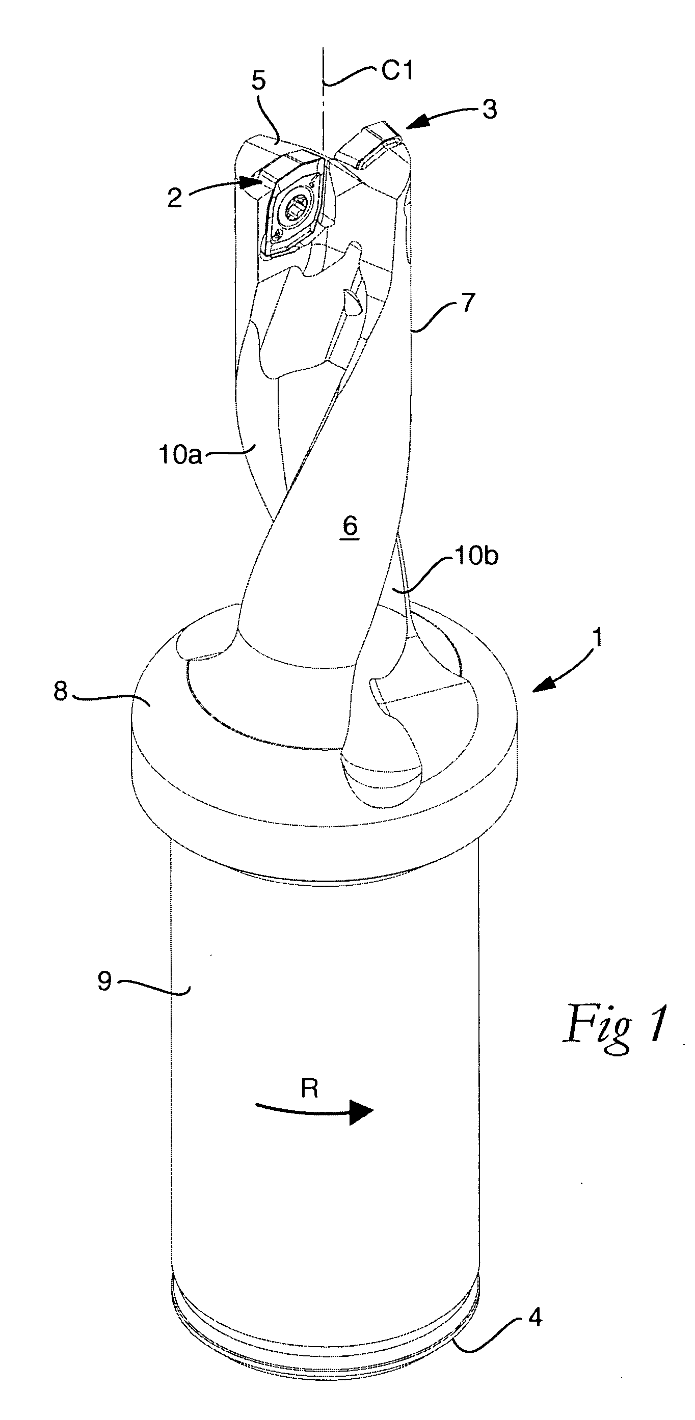
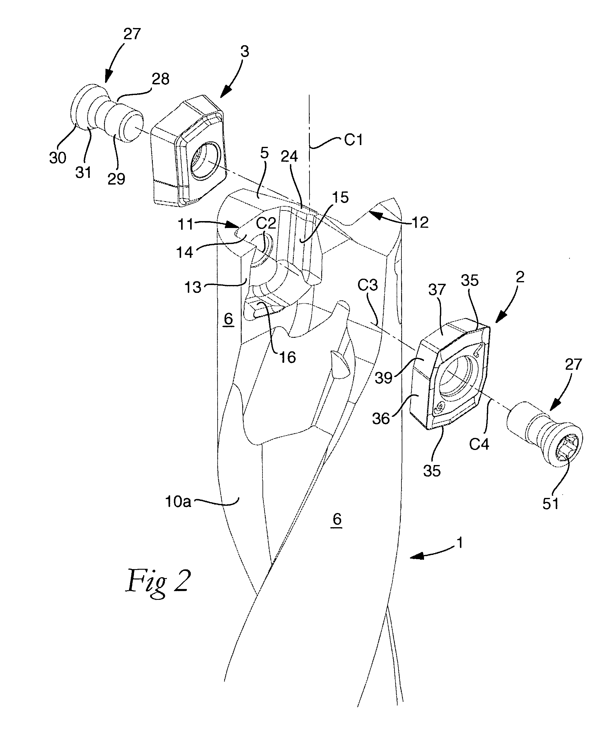
[0023]FIGS. 1 and 2 illustrate an indexable insert drill that includes a basic body or drill body 1, and two cutting inserts 2, 3, one of which is a center insert 2 and the other of which is a peripheral cutting insert 3. The drill body 1 is rotatable in the rotational direction R around a center axis C1, and includes a rear end 4 as well as a front end 5, which is represented by an end surface composed of a plurality of part surfaces. Rearward from the front end 5, an envelope surface 6 extends on a front, cylindrical part 7 of the drill body. The front, shank-like part 7 ends in a collar 8, which in turn transforms into a rear part 9 in the form of a fixing part that is fixable in a machine (not shown). In the part 7, two chip flutes 10a, 10b are formed, which in this case are helicoidal and extend from the front end 5 of the drill body to the collar 8.

[0024]The proper drill body 1 may—but does not need to—be solid and manufactured from, for instance, steel, while the cutting inse...


PUM

PropertyMeasurementUnit
acute angleaaaaaaaaaa
obtuse angleaaaaaaaaaa

Abstract

A drill for chip removing machining, including a drill body that rotates around a center axis (C1) and has a rear end, and a front end from which there extends rearward an envelope surface in which two chip flutes each having an insert pocket are countersunk, and two replaceable cutting inserts, including a peripheral cutting insert mounted in a peripheral pocket, and a center insert, which is indexable and mounted in a center pocket that opens in the front end of the drill body and is delimited by a bottom surface, a rear end support surface, a side support surface of a partition wall, and an inside of a border adjacent to the envelope surface. The center insert includes an upperside and an underside between which a through hole for a tightening screw extends, and has an elongate basic shape that is mirror-symmetrical in relation to an imaginary, longitudinal central plane (P) with which a center axis (C3) of the hole coincides. One of two opposite, longitudinal side contact surfaces of the cutting insert which run parallel to each other and to the central plane (P), are urged against the side support surface of the center pocket. One of the two opposite end surfaces which are formed adjacent to chip-removing cutting edges at the short ends of the center insert, are urged against the rear end support surface of the center pocket. The side support surface of the center pocket is inclined in relation to the center axis (C1) of the drill body at an acute angle (ε) within the range of 3-8°. At each one of two diagonally opposite corners of the center insert, an intermediate surface is formed between the side contact surface and an end surface. The intermediate surface is shorter than the side contact surface and forms an obtuse angle (α) with the side contact surface. One of the intermediate surfaces is located in an area of a clearance space between the side support surface of the center pocket and the end support surface of the center pocket.

Description

[0001]This application claims priority under 35 U.S.C. § 119 to Swedish Patent Application No. 0700237-1, filed on Jan. 29, 2007, the disclosure of which is incorporated by reference herein in its entirety.FIELD OF THE INVENTION[0002]The present invention relates generally to a drill for chip removing machining of the type that includes, on one hand, a drill body that is rotatable around a center axis and has a rear end and a front end from which there extends rearward an envelope surface in which two chip flutes having an insert pocket each are countersunk, and on the other hand two replaceable cutting inserts, viz. a peripheral cutting insert mounted in a peripheral pocket and a center insert. The center insert is indexable and mounted in a center pocket that opens in the front end of the drill body and is delimited by a bottom surface, a rear end support surface, a side support surface of a central partition wall, and an inside of a border adjacent to the envelope surface. The ce...

Claims


Application Information

Patent Timeline
Patent Type & Authority Applications(United States)
IPC IPC(8): B23B27/16B23B51/00B27G15/00
CPCB23B27/1614B23B51/048B23B2200/125Y10S408/713Y10T407/23Y10T408/868Y10T408/909Y10T408/905Y10T407/2206B23B51/00B23C5/20B23B51/02B23B51/0011B23B51/0008
Inventor LIMELL, MICHAELSJOBERG, SOREN
Owner SANDVIK INTELLECTUAL PROPERTY AB
Why Eureka
Try Eureka