Fuel cell

a fuel cell and cell technology, applied in the field of fuel cells, can solve the problems of easy damage to thin parts b>6/b>, and achieve the effect of reducing the size of resin frame members and reliably maintaining the desired strength

Active Publication Date: 2012-11-22
HONDA MOTOR CO LTD
View PDF7 Cites 6 Cited by
  • Summary
  • Abstract
  • Description
  • Claims
  • Application Information

AI Technical Summary

Benefits of technology

[0010]In the state where the frames 4 are stacked together in the direction indicated by the arrow X, the grooves 5 of the respective frames 4 are overlapped with each other in the stacking direction indicated by the arrow X. Thus, thin portions 6 of the frames 4 are overlapped with each other, and stress concentration tends to occur in the thin portions 6. As a result, the thin portions 6 can be damaged easily. In this regard, in order to ensure that the thin...

Problems solved by technology

As a result, the thin po...

Method used


Image

  • Fuel cell
  • Fuel cell
  • Fuel cell

Examples


Embodiment Construction

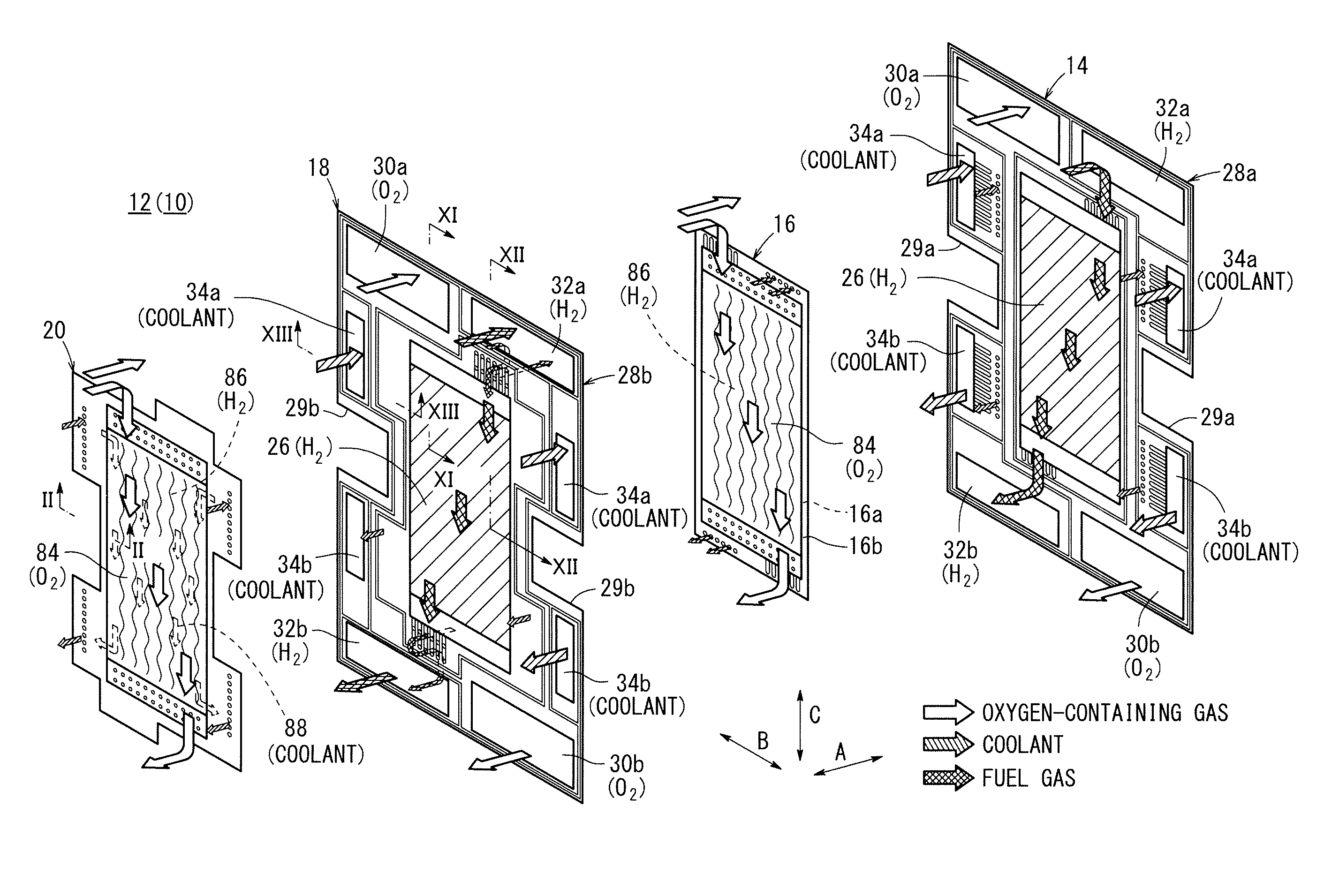
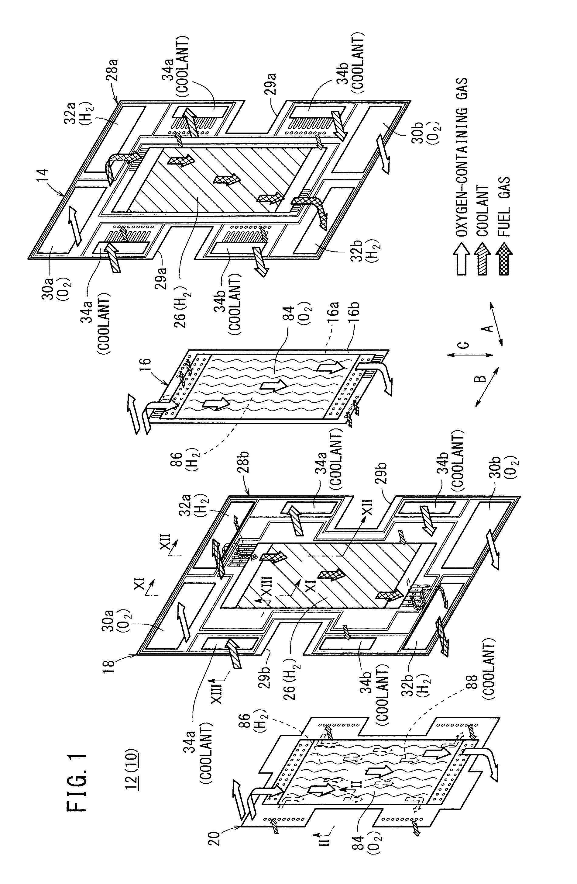
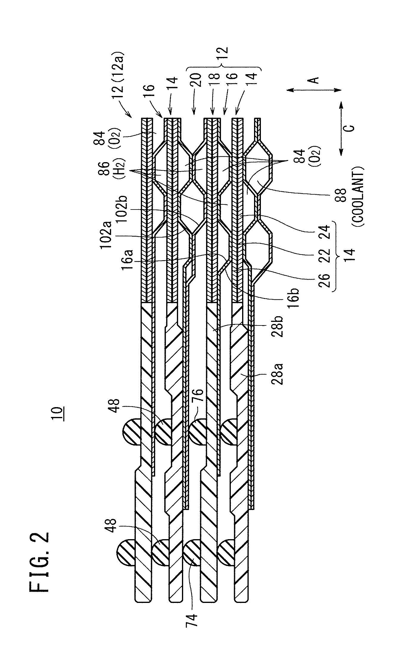
[0033]As shown in FIGS. 1 and 2, a fuel cell 10 according to a first embodiment of the present invention is formed by stacking a plurality of cell units 12 (including a cell unit 12a to be described later) in a horizontal direction indicated by an arrow A.

[0034]The cell unit 12 includes a first membrane electrode assembly (electrolyte electrode assembly) (MEA) 14, a first metal separator 16, a second membrane electrode assembly (electrolyte electrode assembly) (MEA) 18, and a second metal separator 20. By stacking the cell units 12, the first membrane electrode assembly 14 is sandwiched between the second metal separator 20 and the first metal separator 16, and the second membrane electrode assembly 18 is sandwiched between the first metal separator 16 and second metal separator 20.

[0035]Each of the first membrane electrode assembly 14 and the second membrane electrode assembly 18 includes a cathode 24, an anode 26, and a solid polymer electrolyte membrane (electrolyte) 22 interpose...


PUM


Abstract

A cell unit of a fuel cell includes a first membrane electrode assembly, a first metal separator, a second membrane electrode assembly, and a second metal separator. Resin frame members are provided at the outer ends of the first and second membrane electrode assemblies. Coolant connection channels including a plurality of grooves is formed in each of the resin frame members. The grooves of the coolant connection channels of the cell unit and grooves of coolant connection channels of a cell unit that is adjacent to the cell unit in the stacking direction are offset from each other, and are not overlapped with each other in the stacking direction.

Description

CROSS-REFERENCE TO RELATED APPLICATION[0001]This application is based upon and claims the benefit of priority from Japanese Patent Application No. 2011-113321 filed on May 20, 2011, of which the contents are incorporated herein by reference.BACKGROUND OF THE INVENTION[0002]1. Field of the Invention[0003]The present invention relates to a fuel cell including cell units each formed by stacking an electrolyte electrode assembly and a metal separator. The electrolyte electrode assembly includes a pair of electrodes and an electrolyte interposed between the electrodes. A plurality of fluid flow fields are formed in each of the cell units for allowing fluids of a fuel gas, an oxygen-containing gas, and a coolant to flow along electrode surfaces.[0004]2. Description of the Related Art[0005]For example, a solid polymer electrolyte fuel cell employs a membrane electrode assembly (electrolyte electrode assembly) (MEA) which includes an anode, a cathode, and a solid polymer electrolyte membran...

Claims


Application Information

Patent Timeline
IPC IPC(8): H01M8/04H01M8/24
CPCH01M8/0267H01M8/0273H01M8/0276Y02E60/50H01M8/04089H01M8/242H01M8/04029H01M8/0258H01M8/026H01M8/2457H01M8/2483H01M8/0271
Inventor ISHIDA, KENTAROGOTO, SHUHEISUGITA, NARUTOSHINAKAMURA, TETSUYA
Owner HONDA MOTOR CO LTD
Why Eureka
Try Eureka