
Handheld Pneumatic Tool For Breaking Up Rock
a pneumatic tool and hand-held technology, applied in the direction of percussive tools, manufacturing tools, drilling machines, etc., can solve the problems of large area of broken rock, large explosion/gas expansion, and large explosion/gas expansion, and achieve the effects of easy drilling, high skill level, and portability of the tool
- Summary
- Abstract
- Description
- Claims
- Application Information
AI Technical Summary
Benefits of technology
Problems solved by technology
Method used
Image

Examples
Embodiment Construction
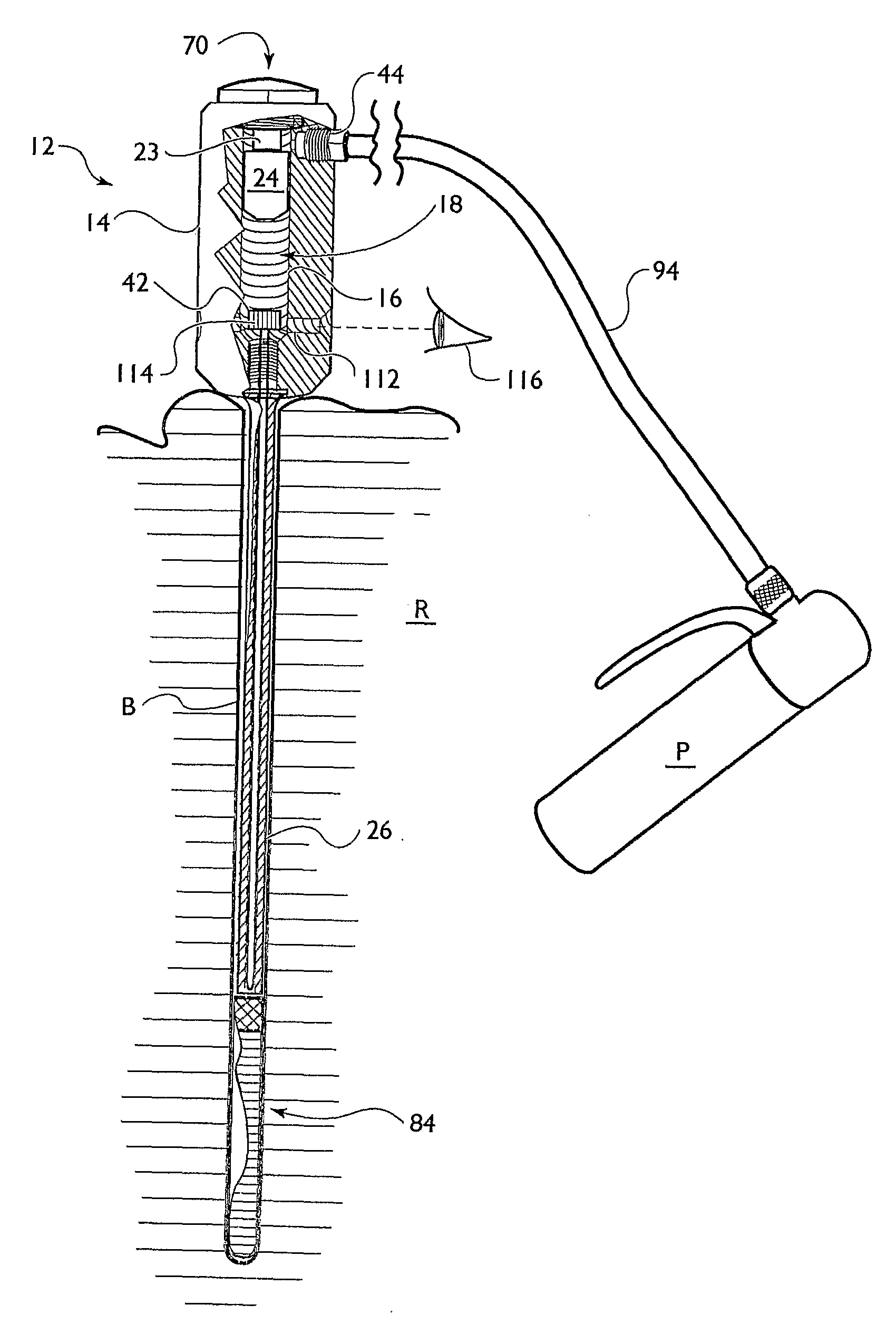
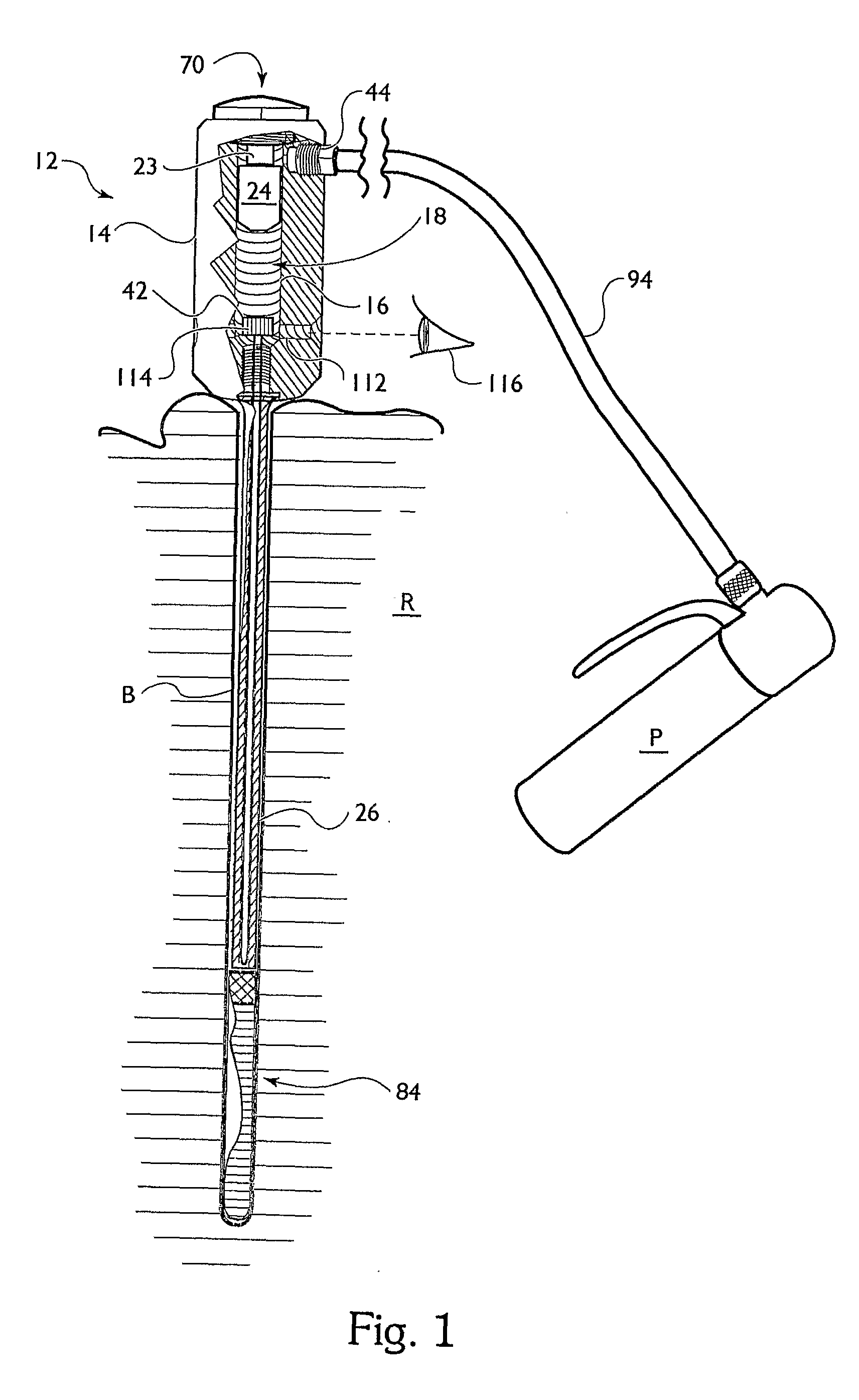
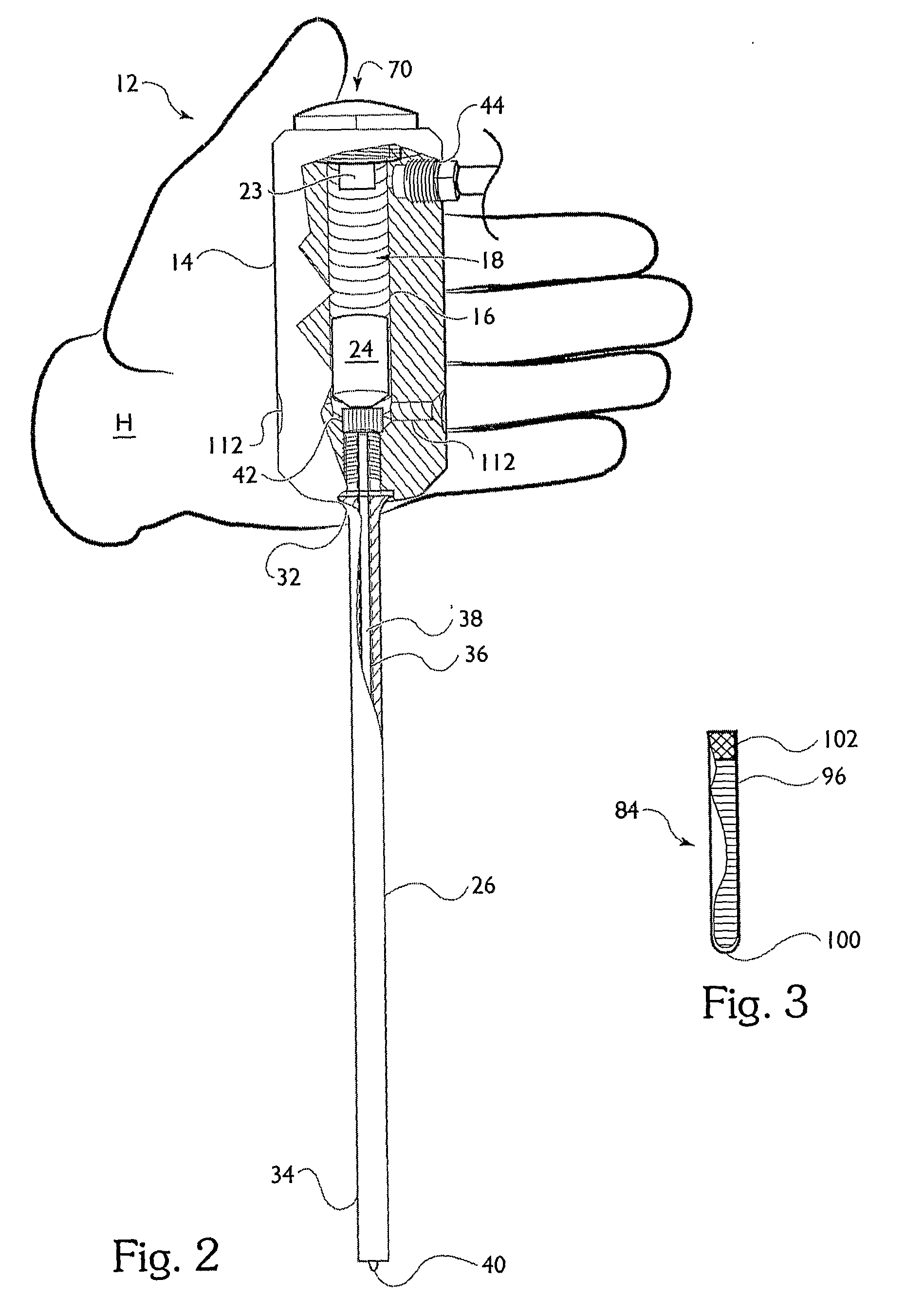
[0044]The present invention relates to a handheld tool (12), a kit containing the tool (110) and a method for the small scale cracking and demolition of solid materials, including by not limited to rock and masonry. The present invention further relates to a pneumatic-magnetic actuator. FIG. 1 shows the tool (12) of the present invention cocked, and ready to be used. FIG. 1 further depicts the tool (12) as used, by showing a cutaway of a borehole (B) in a rock (R) having the tool (12) engaged and a cartridge (84) in the proper position in the borehole (B). FIG. 2 shows the tool (12) in an uncocked or released position. The tool (12) of FIG. 2 is shown relative to an average human hand (H) demonstrating the size of a preferred embodiment of the tool (12) of the present invention. Nonetheless, the tool (12) may be of different dimension and is not restricted to the general size shown. FIG. 3 is a view of the cartridge (84) used with the present invention. The cartridge (84) are also d...
PUM
| Property | Measurement | Unit |
|---|---|---|
| diameter | aaaaa | aaaaa |
| length | aaaaa | aaaaa |
| pressure | aaaaa | aaaaa |
Abstract
Description
Claims
Application Information