Liquid crystal display device

a technology of liquid crystal display and display device, which is applied in the field of liquid crystal display device, can solve the problems of limited power consumption, reduced size and production cost, and high power consumption, and achieve the effect of preventing deterioration of picture quality and reducing unit cos

Active Publication Date: 2008-08-07
LG PHILIPS LCD CO LTD
View PDF10 Cites 7 Cited by
  • Summary
  • Abstract
  • Description
  • Claims
  • Application Information

AI Technical Summary

Benefits of technology

[0009]An object of the present invention is to provide a liquid crystal display device which can

Problems solved by technology

However, because a plurality of data and gate driver integrated circuits, and data printed circuit boards, and the like are provided, the flexible printed circuit and the liqui

Method used


Image

  • Liquid crystal display device
  • Liquid crystal display device
  • Liquid crystal display device

Examples


first embodiment

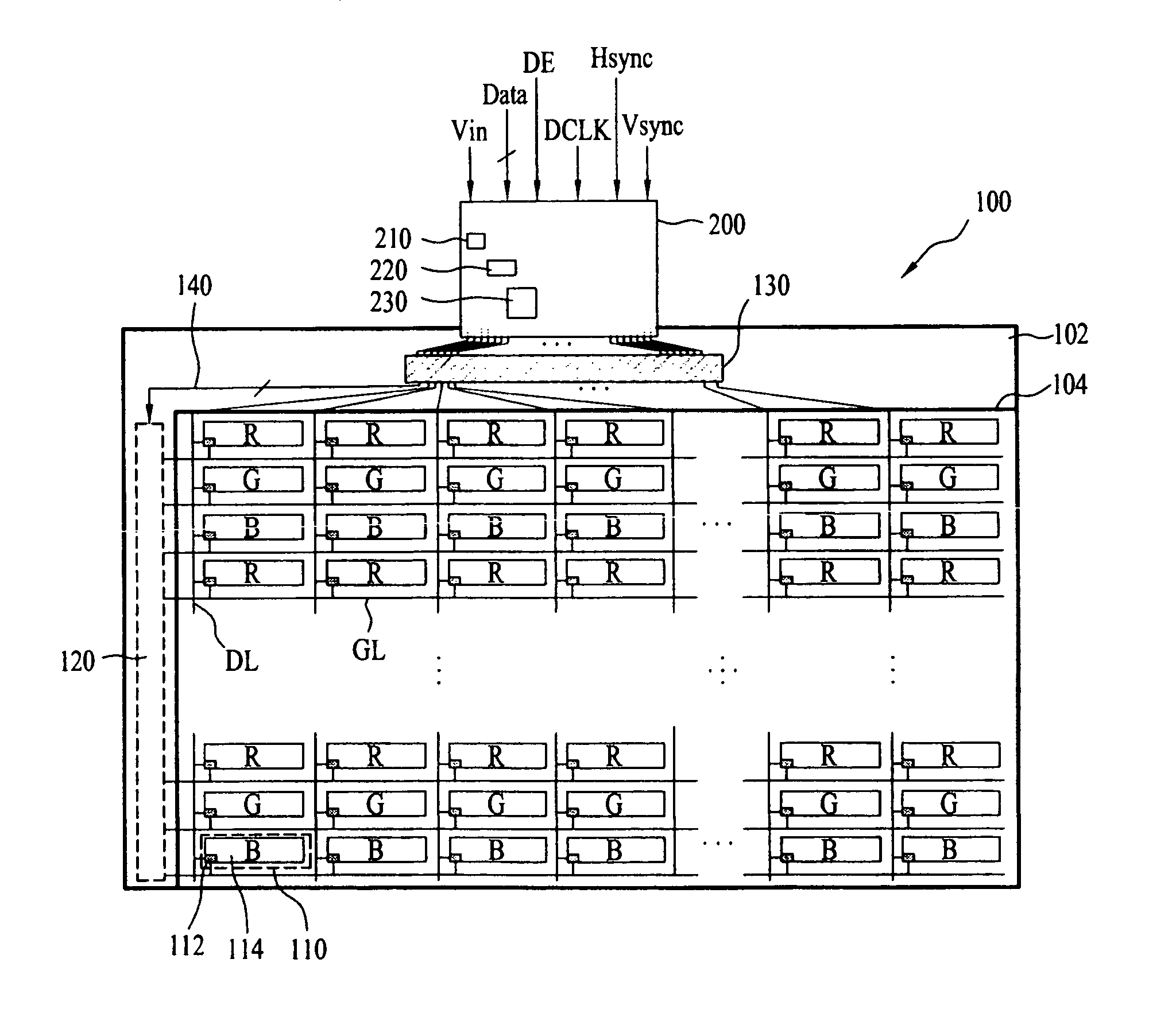
[0073]In the liquid crystal display device according to the present invention, the liquid crystal panel 100 is driven by one driving integrated circuit that is built in the liquid crystal panel 100, so that it is possible to reduce the unit cost and to minimize the thickness of the liquid crystal display device. In addition, the polarity of video signal may be inverted in the unit of data line and three gate lines, thereby improving the picture quality by ensuring the sufficient time for charging the video signal with the minimized polarity change of video signal.

second embodiment

[0074]FIGS. 5A and 5B are diagrams illustrating a polarity pattern of video signal displayed in a liquid crystal panel of a liquid crystal display device according to the present invention.

[0075]As shown in FIGS. 5A and 5B in association with FIG. 1, except for the polarity pattern of video signal displayed on the liquid crystal display panel, the liquid crystal display device according to the second embodiment of the present invention is identical to that according to the first embodiment of the present invention. Accordingly, a detailed understanding of the identical structural elements may be appreciated from the above description associated with FIGS. 1 to 4. In the liquid crystal display device according to the second embodiment of the present invention, a driving integrated circuit 130 inverts the polarity of video signal in the unit of each data line DL and in the unit of four gate lines GL; and supplies the video signal having the inverted polarity to the data lines DL. Acco...

third embodiment

[0076]FIGS. 6A and 6B are diagrams illustrating a polarity pattern of video signal displayed in a liquid crystal panel of a liquid crystal display device according to the present invention.

[0077]As shown in FIGS. 6A and 6B in association with FIG. 1, except for the polarity pattern of video signal displayed on the liquid crystal display panel, the liquid crystal display device according to the third embodiment of the present invention is identical to that according to the first embodiment of the present invention. Accordingly, a detailed understanding of the identical structural elements may be appreciated from the above description associated with FIGS. 1 to 4. In the liquid crystal display device according to the third embodiment of the present invention, on assumption that there are ‘n’ gate lines, a driving integrated circuit 130 inverts the polarity of video signal in the unit of each data line DL and in the unit of ‘n / 2’ gate lines; and supplies the video signal having the inv...


PUM


Abstract

A liquid crystal display device is disclosed, which can reduce a unit cost and prevent deterioration of picture quality caused by unfilled pixel cells, the liquid crystal display device comprising a liquid crystal panel including a plurality of pixel cells formed at every regions defined by ‘n’ gate lines and ‘m’ data lines, three colors alternatively arranged along the data line direction, and the same colors arranged along the gate line direction; a gate built-in circuit, built-in the liquid crystal panel, for supplying gate-on voltages to the gate lines; and a driving integrated circuit, formed in the liquid crystal panel, for driving the gate built-in circuit, inverting a polarity of video signal in the unit of each data line and at least three gate lines, and supplying the video signal having the inverted polarity to the data lines.

Description

[0001]This application claims the benefit of Korean Patent Application No. 10-2007-0010487 filed Feb. 1, 2007 which is hereby incorporated by reference as if fully set forth herein.BACKGROUND OF THE INVENTION[0002]1. Field of the Invention[0003]The present invention relates to a liquid crystal display (LCD) device, and more particularly, to a liquid crystal display device which can reduce a unit cost and prevent deterioration of picture quality caused by unfilled pixel cells.[0004]2. Discussion of the Related Art[0005]In general, a liquid crystal display device controls an optical transmission ratio of liquid crystal molecules by using an electric field applied thereto, to thereby display desired images. For this, the liquid crystal display device is provided with a liquid crystal panel having liquid crystals between two glass substrates, a plurality of liquid crystal cells arranged in a matrix configuration, and switching devices to respectively change signals supplied to the liqui...

Claims


Application Information

Patent Timeline
IPC IPC(8): G02F1/141
CPCG02F1/13452G09G2310/0297G09G3/3614G02F1/13454A47J43/28
Inventor PARK, CHANG KEUN
Owner LG PHILIPS LCD CO LTD
Why Eureka
Try Eureka