Single cycle dart operated circulation sub

a single-cycle dart and circulation sub technology, applied in the direction of fluid removal, wellbore/well accessories, sealing/packing, etc., can solve the problems of easy eroded balls, difficult to know, and less suitable valves for deviating wellbores

Inactive Publication Date: 2008-08-14
BAKER HUGHES INC
View PDF51 Cites 34 Cited by
  • Summary
  • Abstract
  • Description
  • Claims
  • Application Information

AI Technical Summary

Problems solved by technology

These types of valves are less suitable for deviated wellbores where it is difficult to know if picking up and setting down has actually shifted the circulation valve or merely stretched the tubing string from a location near a wellbore deviation.
The problem with this design is that the balls are rather soft and are prone to be eroded during delivery or even when on the ball seat itself and before the operation that depends on the ball sealing can be accomplished.
Other issues that have affected ball seats made of a series of collets is that the sealing happens on a series of abutting shoulders and in a downhole environment where debris can settle on the seating surface and reduce the chance for a good seal on the ball.
Additionally, the collets have some gaps between them where some of the applied pressure creates a bypass flow that inhibits the desired shifting movement of a sleeve.
The release of the initial ball that opened the circulation port could lodge in the packer below and cause it to set prematurely.

Method used


Image

  • Single cycle dart operated circulation sub
  • Single cycle dart operated circulation sub
  • Single cycle dart operated circulation sub

Examples


Embodiment Construction

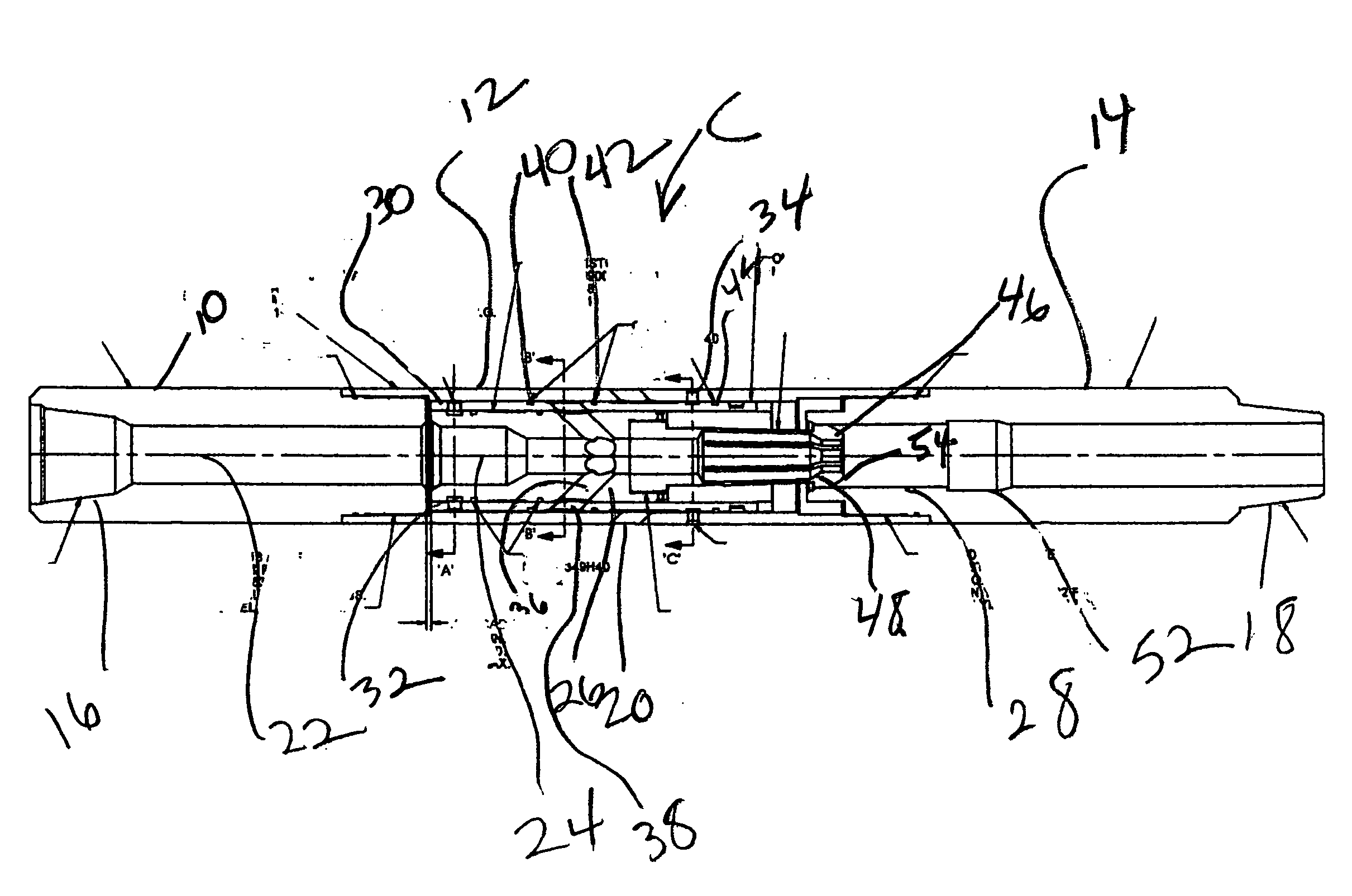
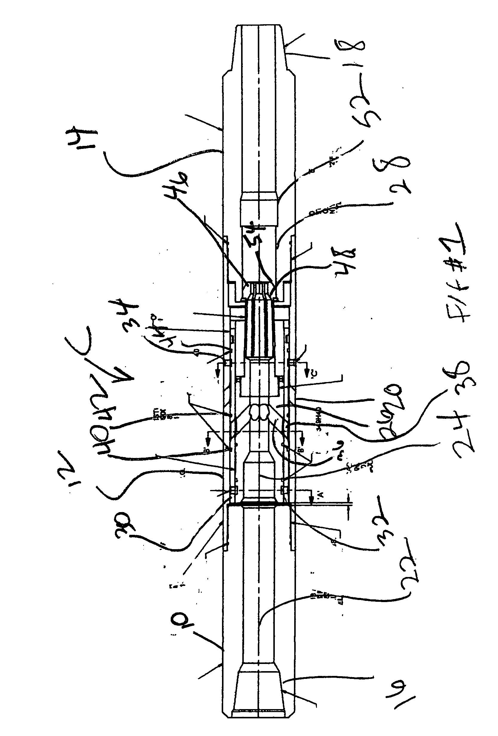
[0017]FIG. 1 illustrates the circulation sub C of the present invention in the run in position. It has a top sub 10 attached to a ported sub 12 which is in turn attached to a bottom sub 14. Thread 16 connects to the string above (not shown). Located above circulation sub C can be other subs that operate just like it but with larger diameter darts.

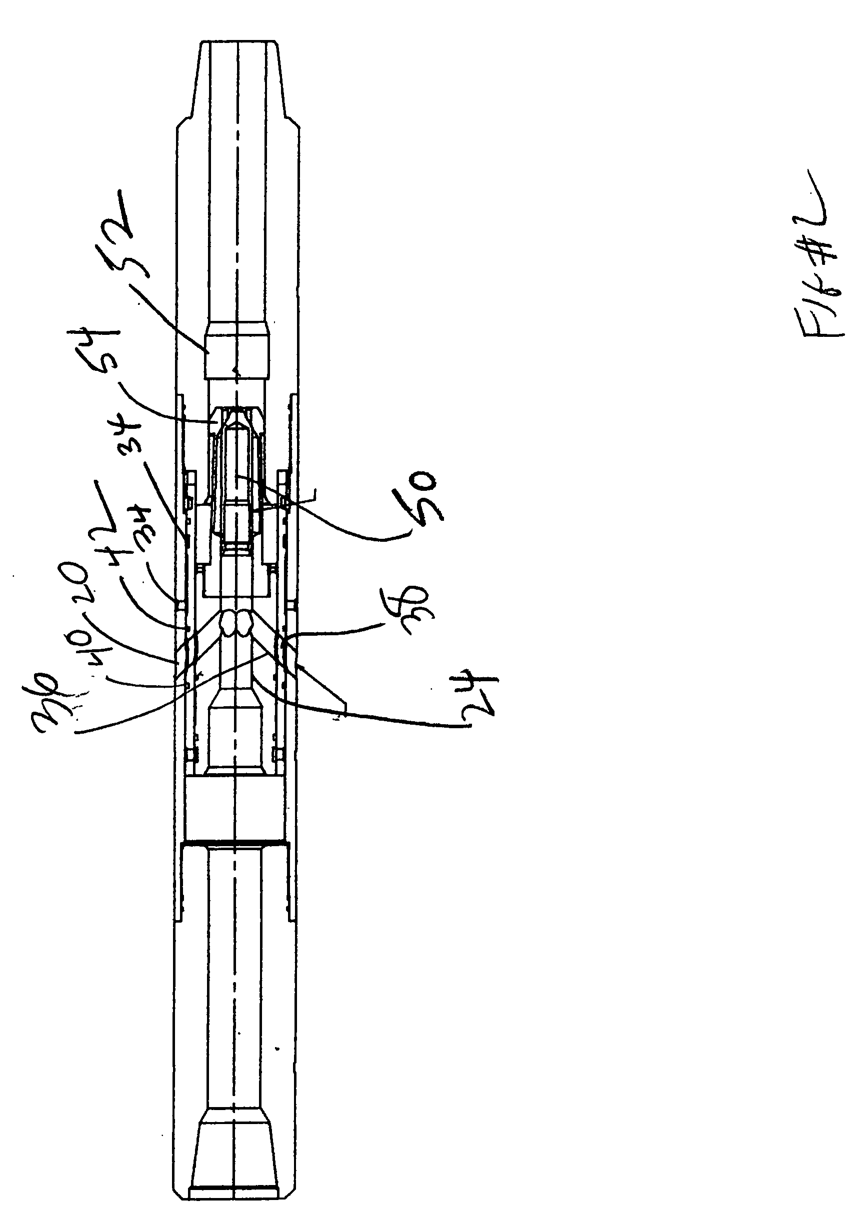
[0018]Thread 18 is used to secure a lower string which can include a packer and dart catchers as will be described below. Ported sub 12 has a port 20. A through passage in circulation sub C comprises an upper passage 22 in top sub 10. Passage 24 in inner piston 26 is the continuation of passage 22. Finally, passage 28 in bottom sub 14 marks the lower end of the through bore in the circulation sub C.

[0019]Outer piston 30 is concentric with inner piston 26 and they are held together by one or more shear pins 32. Outer piston 30 is also held to ported sub 12 by one or more shear pins 34 that are preferably weaker than pins 32. In the run in po...


PUM


Abstract

A circulating sub is run in with the circulating port closed. A dart blocks a central passage and moves two concentric pistons in tandem to open the circulation port while retaining the dart. The outer piston shoulders out in the circulation port open position. A second dart lands on the first and with applied pressure moves the inner piston relative to the shouldered outer piston to close the circulation port and only then discharge both darts. Subs can be used in tandem as long as higher located subs accept larger darts than lower subs and preferably the two darts for each sub are the same size. The ejected darts can be used to pressure actuate a downhole tool like a packer.

Description

FIELD OF THE INVENTION[0001]The field of this invention is downhole circulation valves that can be opened and closed with dropped objects and more particularly to valves that can open and close without having to use a larger object for a second position of the valve.BACKGROUND OF THE INVENTION[0002]There are many operations downhole that require circulation or reverse circulation through a tool string. Almost as often the circulation valve needs to be operated between two positions so that, for example, it can be run in open to the desired location and then after the circulation is done, it can be closed again.[0003]There are many types of circulation valves that are in use downhole. Some have an internal ported sleeve that is attached to a housing with a port through a j-slot mechanism. With this type of valve picking up and setting down weight gets the ports aligned or misaligned, as needed. These types of valves are less suitable for deviated wellbores where it is difficult to kn...

Claims


Application Information

Patent Timeline
Patent Type & Authority Applications(United States)
IPC IPC(8): E21B41/00E21B34/00
CPCE21B21/103
Inventor POSEVINA, LISA L.HERN, GREGORY L.
Owner BAKER HUGHES INC
Why Eureka
Try Eureka