Method for determining a highly accurate position of routes and/or objects

a highly accurate and route-oriented technology, applied in vehicle position/course/altitude control, process and machine control, instruments, etc., can solve the problems of inability to increase the accuracy, inaccuracy of digital rail maps, and inapplicability of digital maps created in this manner

a highly accurate and route-oriented technology, applied in vehicle position/course/altitude control, process and machine control, instruments, etc., can solve the problems of inability to increase the accuracy, inaccuracy of digital rail maps, and inapplicability of digital maps created in this manner

US20080208520A1Inactive Publication Date: 2008-08-28DEUTSCHES ZENTRUM FUER LUFT & RAUMFAHRT EV

Image

  • Method for determining a highly accurate position of routes and/or objects
  • Method for determining a highly accurate position of routes and/or objects
  • Method for determining a highly accurate position of routes and/or objects

Examples


Embodiment Construction

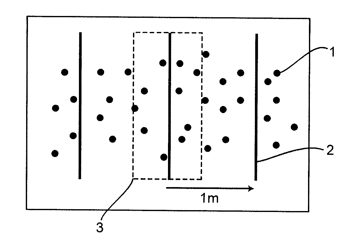
[0027]FIG. 1a diagrammatically shows a plurality of measured values 1 which were determined when surveying a route. In this case, a plurality of surveying operations were carried out and the measured values recorded in the individual surveying operations were then superimposed, as illustrated in FIG. 1a. Corresponding planes 2 which are defined perpendicular to the course of the route were then placed in these measured values which were superimposed in this manner. These planes 2 can be placed in the measured value series at a distance of one meter, for example, as illustrated in the exemplary embodiment of FIG. 1a.

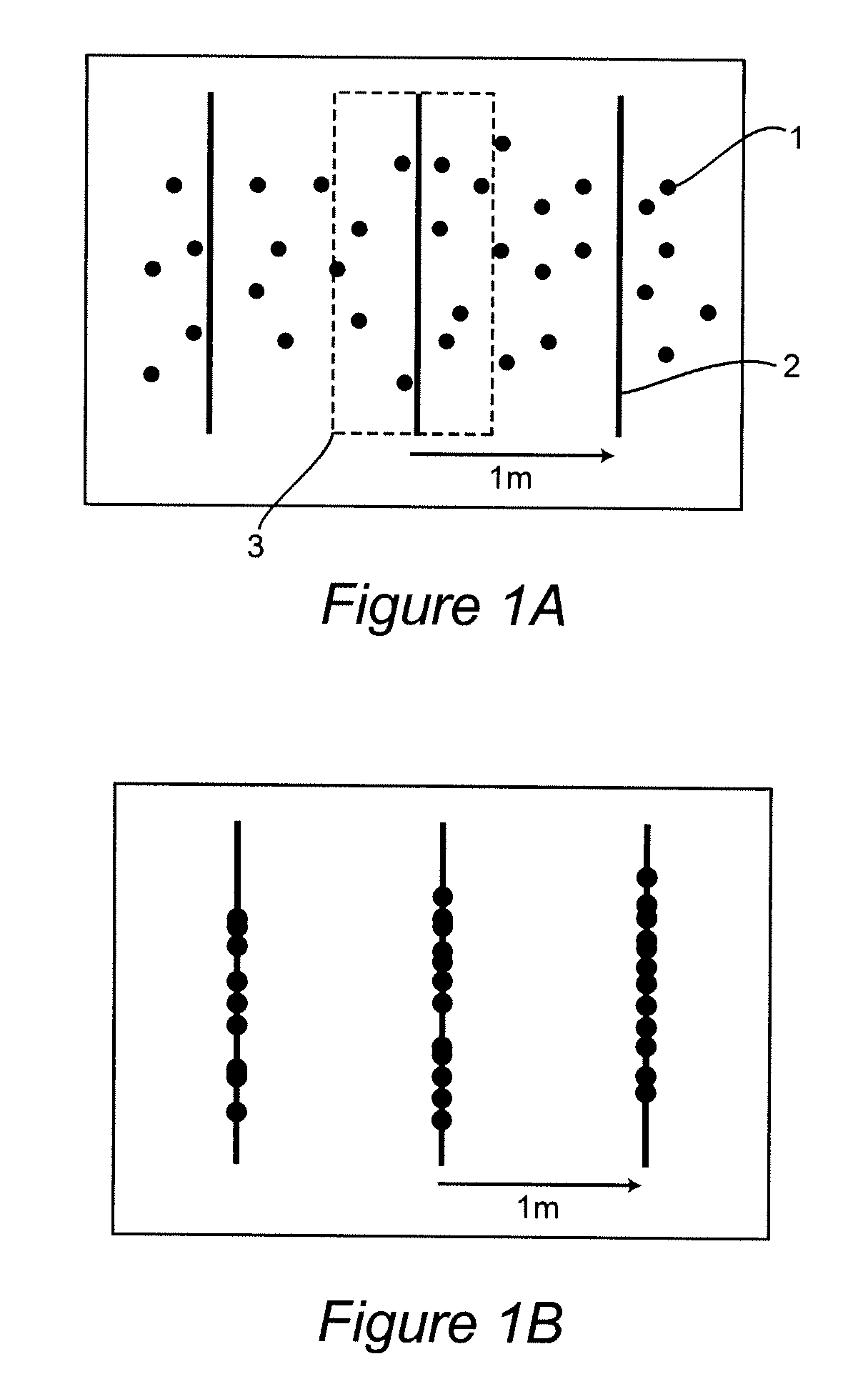
[0028]Each of these planes 2 forms a region 3 around itself. The measured values in this region 3 are then projected onto the corresponding plane, as shown in FIG. 1b. In this exemplary embodiment, this means that the measured values are horizontally shifted onto the corresponding planes in the direction of the route. After this step, bundling of the measured values on t...


PUM


Abstract

The invention relates to a method for determining a highly accurate position of routes and / or objects, in which the routes and / or objects to be recorded are first of all surveyed. In this case, the teaching provides for the routes and / or objects to be recorded to be surveyed repeatedly and for the positions to be determined with the aid of statistical methods using measured values obtained by the repeated surveying operation.

Description

BACKGROUND OF THE INVENTION[0001]1. Field of the Invention[0002]The invention relates to a method for determining a highly accurate position of routes and / or objects, in which the routes and / or objects to be recorded are first of all surveyed.[0003]2. Description of the Related Art[0004]In order to create digital maps, it is necessary for the routes which are contained in the map, for example roads or rails, and possibly also objects, for example landmarks, bridges or known buildings, to be first of all surveyed in order to determine their position. The corresponding route or the corresponding object is entered in the map using this position.[0005]In this case, routes are usually surveyed with the aid of appropriately converted vehicles which travel along a route to be surveyed and in the process continuously determine the position with the aid of position-finding systems, in particular satellite position-finding systems. This is known, for example, from the “StreetMapper” project (...

Claims


Application Information

Patent Timeline
28 Aug 2008
Publication
US20080208520A1
IPC
G06F15/00
CPC
G01C21/26
Inventors
NOYER, ULF; NIEHOFF, NICO