Assembly for an Angular Position Measuring Device

Active Publication Date: 2011-10-20
DR JOHANNES HEIDENHAIN GMBH
View PDF12 Cites 6 Cited by
  • Summary
  • Abstract
  • Description
  • Claims
  • Application Information

AI Technical Summary

Benefits of technology

[0007]Example embodiments of the present invention provide an assembly for an angular position measuring device, by which high measuring accuracy is reliably and long-lastingly attainable.
[0012]For example, the contact surface and the ring are machined such that the section in which the contact surface touches the ring acts like a seal, especially for the lubricant. In this manner, it is possible to dispense with additional joint gaps or seals, which leads to a more precise structural form of the assembly, and as a result, minimizes the measuring errors of the corresponding angular position measuring device.

Problems solved by technology

It may be particularly disadvantageous if lubricant or components thereof escape from the roller bearing and deposit on the measuring standard, especially in the area of the angle scaling.
Under such circumstances, the light beams are deflected accordingly, which can lead to a faulty measurement.
An assembly of this kind has the disadvantage that it is generally accompanied by comparatively great measuring errors.
The reason is that on one hand, there is the danger that the measuring standard will not be centered with sufficient precision relative to the axis of rotation, and in addition, that wobble errors will occur.

Method used


Image

  • Assembly for an Angular Position Measuring Device
  • Assembly for an Angular Position Measuring Device
  • Assembly for an Angular Position Measuring Device

Examples


Embodiment Construction

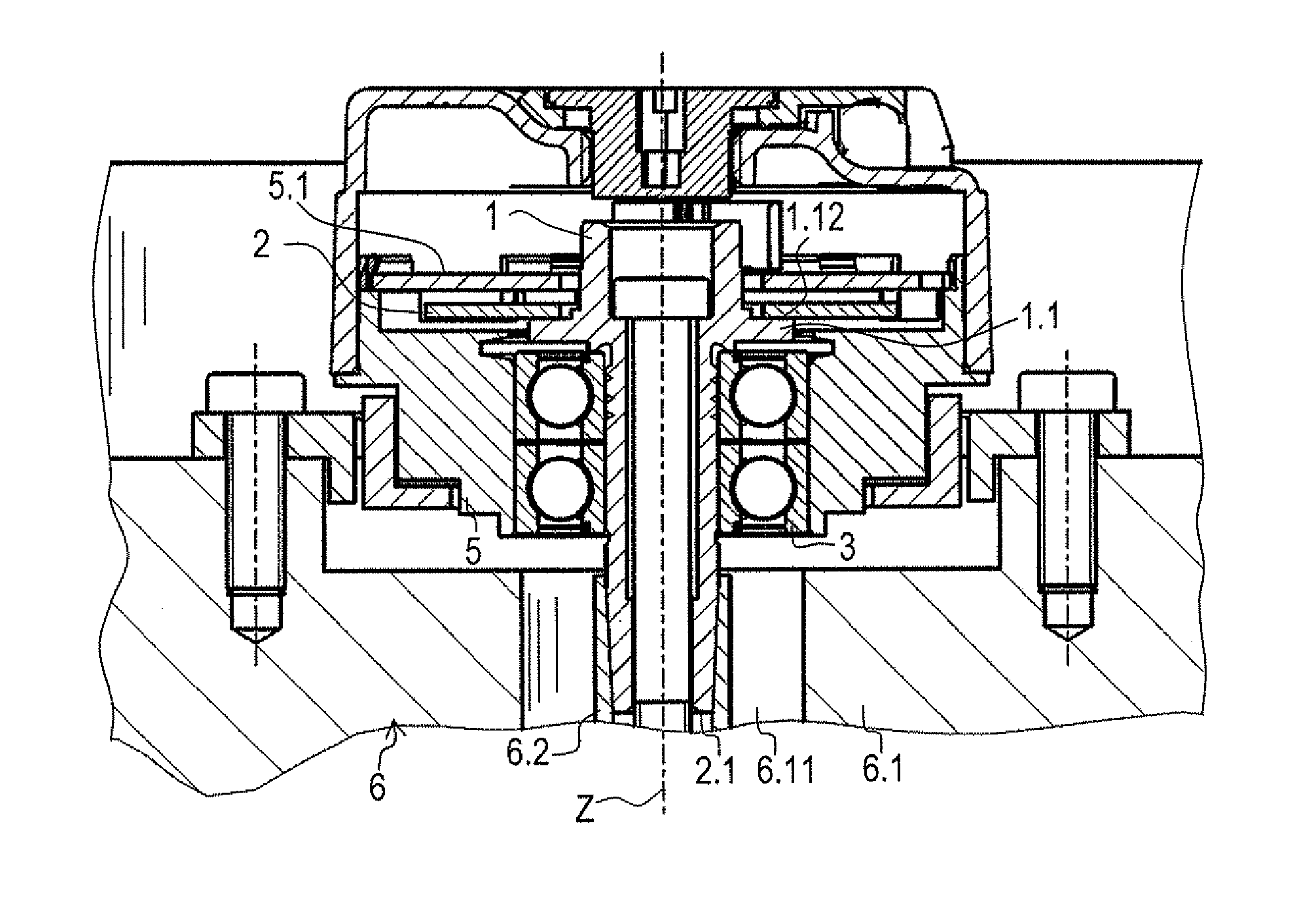
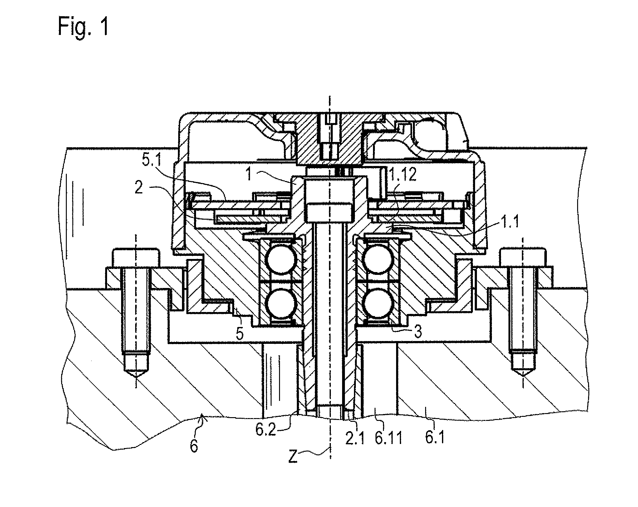
[0039]The angular position measuring device, shown in a center longitudinal cross-sectional view in FIG. 1, includes a stator and a rotor. The rotor has a one-piece shaft 1 having a shoulder 1.1 that is machined out of a monolithic semi-finished product with the aid of a turning operation. Shoulder 1.1 has a joining surface 1.12 oriented orthogonally with respect to axis Z (see also FIG. 2). On it, a measuring standard 2 is fixedly joined by an adhesive, in a centric manner relative to axis Z and with only slight tolerance deviations. Measuring standard 2, on which an angle scaling 2.1 is applied, is ring-shaped and made of glass, measuring standard 2 being produced with high precision in terms of its dimensional accuracy and planarity. Angle scaling 2.1 is illustrated in FIG. 2. For example, it may be implemented as an incremental graduation having radially oriented scale lines, or as an absolute code. Shaft 1 is rotationally mounted by a bearing, here two roller bearings 3, within...


PUM


Abstract

An assembly for an angular position measuring device includes a shaft having a measuring standard for measuring a rotational movement about an axis. The shaft has a shoulder as an integral component, on which a roller bearing is mounted in axial abutment. Arranged between the shoulder of the shaft and the roller bearing is a groove which is oriented with a radial directional component and is connected to a hollow space for receiving lubricant, the hollow space being bounded in the radial direction by a ring of the roller bearing and by the shaft.

Description

CROSS-REFERENCE TO RELATED APPLICATIONS[0001]The present application claims priority to Application No. 10 2010 027 900.5, filed in the Federal Republic of Germany on Apr. 19, 2010, which is expressly incorporated herein in its entirety by reference thereto.FIELD OF THE INVENTION[0002]The present invention relates to an assembly for an angular position measuring device.BACKGROUND INFORMATION[0003]Angular position measuring devices, also frequently referred to as rotary encoders, are used to measure rotational movements of a rotationally mounted machine part, particularly a shaft, over one or more revolutions. In so doing, the rotational movement is recorded incrementally or absolutely. In connection with gear racks and gear wheels or with threaded spindles, linear motions can also be measured by an angular position measuring device. Such angular position measuring devices are often used in conjunction with electric motors to generate a commutation signal.[0004]As a rule, angular pos...

Claims


Application Information

Patent Timeline
IPC IPC(8): G01B7/30
CPCF16C3/02G01D3/028F16N2210/14F16C33/66
Inventor MEYER, HERMANN
Owner DR JOHANNES HEIDENHAIN GMBH
Why Eureka
Try Eureka