
Device for measuring time-resolved volumetric flow processes

a technology of volumetric flow and process, which is applied in the direction of machines/engines, instruments, and individual entry/exit registers. it can solve the problems of inability to accurately measure post-injection and its pattern analysis, inability to accurately measure, and inability to meet the current conditions. achieve the effect of high measuring accuracy and simple design

Inactive Publication Date: 2007-08-14
AVL LIST GMBH
View PDF16 Cites 8 Cited by
  • Summary
  • Abstract
  • Description
  • Claims
  • Application Information

AI Technical Summary

Benefits of technology

The invention is a device for measuring the flow of fluids in combustion engines with high accuracy. It is designed to measure the injection process of fuel into the engine in real-time and with high precision. The device can measure the amount of fuel injected and the pattern of injection continuously and accurately. It uses a pressure sensor and a displacement sensor to measure the piston displacement and the volume difference between two parts. The device can be positioned before the injection valve and can measure the injection amount and pattern of multiple injections. It is advantageously easy to install and can be used on both new and running engines. The device can also be used to measure the temperature and pressure of the fluid being measured. Overall, the invention provides a simple yet highly accurate device for measuring the flow of fluids in combustion engines.

Problems solved by technology

However, due to the inertia of the piston mass and the occurring friction, measuring inaccuracies occur in this method that are too great for present-day conditions.
While it is true that more accurate measuring results can be achieved by this due to the smaller total volumes to be measured, the problem of the relatively large piston mass to be moved still remains, so that vibrations and delays occur in the system as before.
Thus, accurate measuring for example of a post-injection and its pattern analysis is not possible.
Moreover the discharge of the respective measuring piston takes place with a discharge valve, so that injections following in very quick succession, as are usual in the normal operation of a combustion engine, cannot be resolved.
In spite of this improved reproducibility of the starting position of the piston, the susceptibility of the system to vibration remains disadvantageous, not least due to the relatively large piston mass.
Moreover, a resolution of closely-spaced individual injections and their patterns remains impossible due to the inertia of the total system.
By means of such an embodiment it is indeed possible to resolve the injection processes with respect to the main or pre- or post-injection, but a quantitative statement about the injection patterns during for example a main injection remains impossible, since no continuous measurement of amounts is present.
Moreover, such a design is not suitable for carrying out measurements on the engine while it is running, since several successive work cycles cannot be measured at that speed.
The design is very complex, however, so that a large number of influencing variables reduce the measuring accuracy and reliability of the plant.
Also, it is not possible to use such a device on an engine while it is running.
Due to its extremely low inertia, this measuring instrument is optimally suited for the immediate measurement of flows, but is not capable of reading synchronous-cycle flow rate information.
This means that it is not possible to show the exact patterns of the injection processes to be measured and their periodicity simultaneously with the work cycle of a four-stroke or diesel engine.
This has the disadvantage that a flow rate measurement in combination with an optical analysis of the spread of an injection jet is not possible.
Moreover, measuring accuracy is further limited.
Due to the inertia of the piston and the fact that the physical properties of the injected fluid are not taken into consideration, the measurement of injected amounts with such a device gives insufficiently accurate measuring results.

Method used


Image

  • Device for measuring time-resolved volumetric flow processes
  • Device for measuring time-resolved volumetric flow processes

Examples


Embodiment Construction

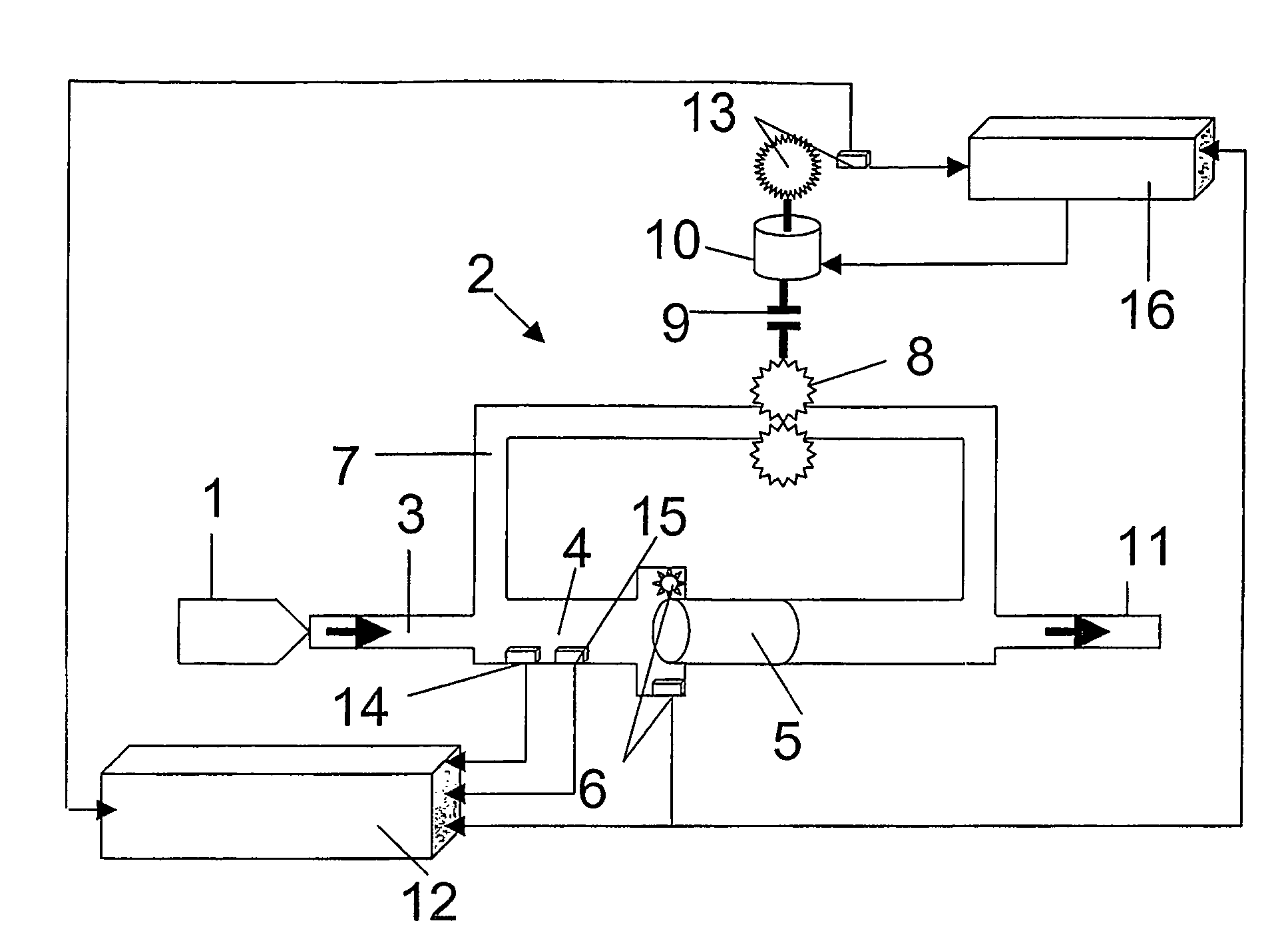
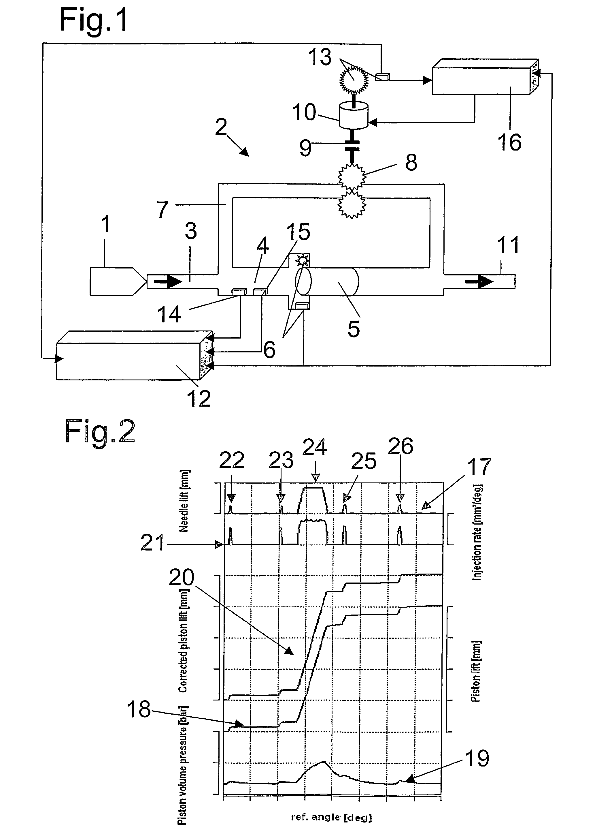
[0030]FIG. 1 shows a design for measuring injection processes in combustion engines with a device according to the invention for measuring time-resolved volumetric flow processes. It is composed of an apparatus, not shown, that produces a flow, in this case as a rule a high-pressure pump, and a fuel injection valve 1, via which fuel is injected into the measuring device 2. The measuring device 2 is composed of an intake duct 3 in which a measuring chamber 4 is arranged, in which again a piston 5 is arranged so that it is free to slide, whereby the piston 5 has the same specific weight as the fluid to be measured, i.e., the fuel. This piston 5 in the measuring chamber 4 serves as a translatory volume difference sensor. On the measuring chamber 4 a sensor 6 is arranged that is in interactive connection with the piston 5 and in which through the displacement of the piston 5 a voltage is produced that is dependent on the magnitude of the displacement of the piston 5.

[0031]In addition, a...


PUM


Abstract

The invention relates to a device for measuring time-resolved volumetric throughflow processes, especially injection process in internal combustion engines, having a translational volume difference sensor having a piston disposed in a measuring compartment and a detection device detecting the excursion of the piston, the detection device being linked with an evaluation unit. According to the invention, a pressure sensor is mounted in the measuring compartment in addition to the detection device which detects the excursion of the piston. The signal of the detection device corresponding to the excursion of the piston can be better evaluated as the compressivity of the fluid in the measuring compartment can be taken into consideration for the calculation of the amount to be injected. The inventive device allows for a highly time-resolved representation of throughflow processes so that both overall amount and exact course of the throughflow can be represented and evaluated.

Description

[0001]This invention claims priority of PCT / EP2004 / 007353, filed on Jul. 6, 2004, which in turn claims priority on DE 10331228.5 filed on Jul. 10, 2003, the entire disclosures of which are incorporated herein by reference.FIELD OF THE INVENTION[0002]The invention relates to a device for measuring time-resolved volumetric flow processes, in particular of injection processes in internal combustion engines with a translatory volume difference sensor that is composed essentially of a piston arranged in a measuring chamber and a data acquisition device that senses the displacement of the piston, which data acquisition device is connected to an evaluation unit.BACKGROUND OF THE INVENTION[0003]Particularly in the area of direct-injection internal combustion engines that work by the diesel or four-stroke cycle method, the demands on injection systems with respect to the measured-out amount, the time, and the pattern of the injection are increasing continuously. Thus, injection patterns have...

Claims


Application Information

Patent Timeline
Patent Type & Authority Patents(United States)
IPC IPC(8): G01M15/00F02M65/00G01F3/16
CPCA62C99/00F02M65/002G01F3/16G07C9/00103G07C9/00111G07C9/28F02M65/00
Inventor METZLER, RAINERWERNER, MANFREDKAMMERSTETTER, HERIBERT
Owner AVL LIST GMBH
Learn More