Pneumatic tire

a technology of pneumatic tires and tires, applied in the field of pneumatic tires, can solve the problem of tire being subjected to much greater loads

Active Publication Date: 2008-09-04
THE GOODYEAR TIRE & RUBBER CO
View PDF7 Cites 62 Cited by
  • Summary
  • Abstract
  • Description
  • Claims
  • Application Information

AI Technical Summary

Problems solved by technology

Such vehicles present a special challenge to a tire engineer because the performance characteristics desired for highway use are tradeoffs with the performance requirements for off-road use.
Furthermore, when an on/off road all p

Method used


Image

  • Pneumatic tire
  • Pneumatic tire
  • Pneumatic tire

Examples


Embodiment Construction

[0032]The following language is of the best presently contemplated mode or modes of carrying out the invention. This description is made for the purpose of illustrating the general principles of the invention and should not be taken in a limiting sense. The scope of the invention is best determined by reference to the appended claims.

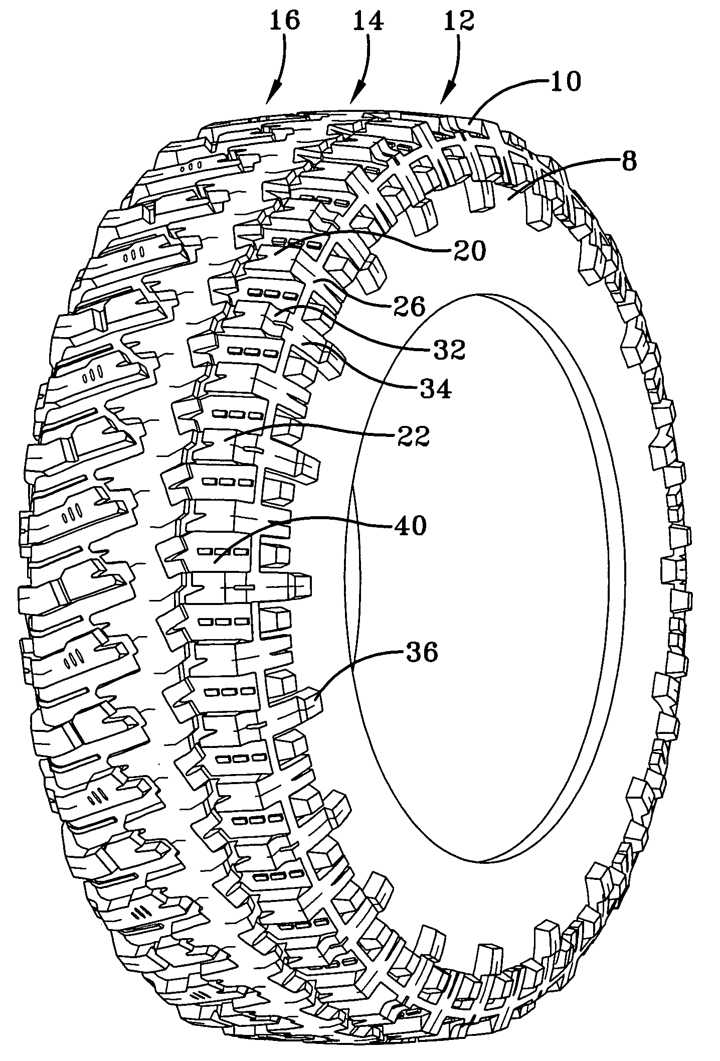
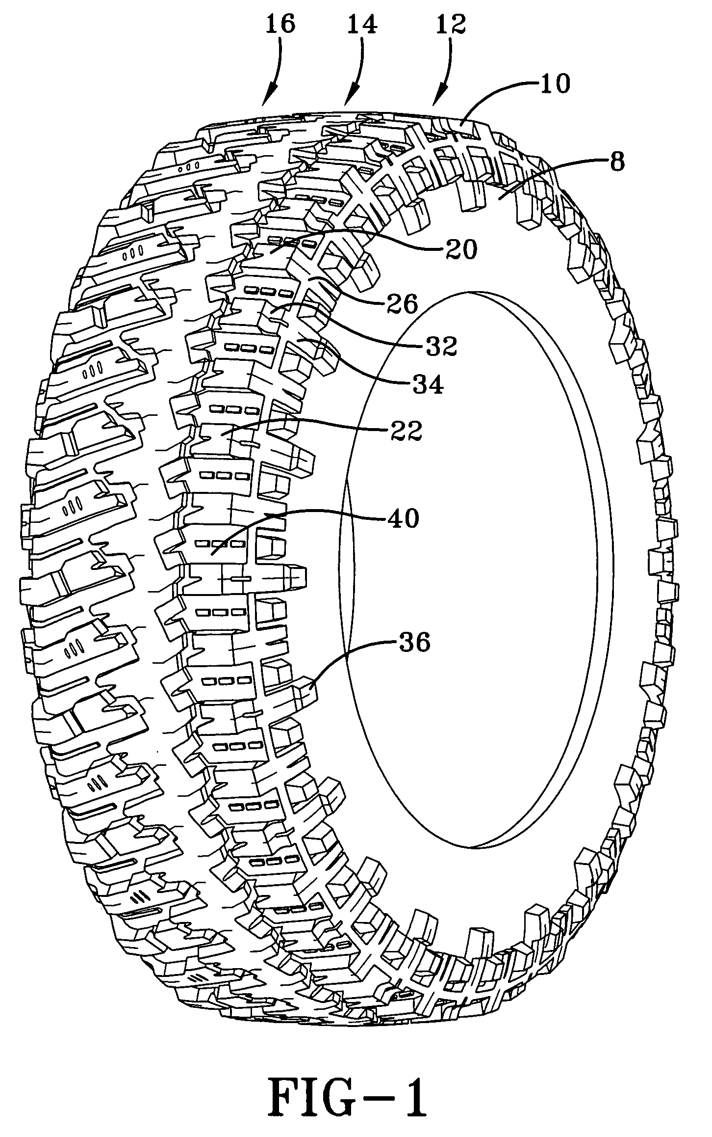
[0033]FIG. 1 illustrates a pneumatic tire having a tread and sidewalls 8. A flat view of the tread is illustrated in FIG. 5. The tire has an asymmetric tread located between a pair of opposing tread edges 10. The sidewalls 8 are axially outward and radially inward of the tread edges 10. The tread has a plurality of traction elements in three defined tread regions: a first edge region 12, a central region 14, and a second edge region 16. In each tread region 12, 14, 16, the traction elements are distinct from the traction elements in the other tread regions.

[0034]The first edge region 12 extends axially inward from a first tread edge 10. Initiating at sh...


PUM


Abstract

A tire has a tread and a pair of opposing shoulders. In the first sidewall, a series of extension blocks creates a pair of concentric rings. In the second sidewall, a different configuration of extension blocks may be present. The second sidewall has alternating extension blocks where one of the blocks has a portion that is located radially inward of the other block.

Description

[0001]This application claims the benefit of, and incorporates by reference, U.S. Provisional Application No. 60 / 904,494 filed Mar. 2, 2007.FIELD OF THE INVENTION[0002]The present invention relates to a pneumatic tire. More particularly, the present invention is directed to a pneumatic tire having defined features in the tires sidewalls and tire tread.BACKGROUND OF THE INVENTION[0003]In a conventional pneumatic tire, particularly a high-performance tire, the tread pattern is generally formed by combining circumferential grooves extending along the circumferential direction of the tire with a plurality of grooves inclined relative to the circumferential direction. The combination of grooves forms a plurality of tread blocks along the radially outer surface of tire. If the inclined grooves do not extend completely across the equatorial plane of the tire, a central rib may be formed in the tread.[0004]A very popular class of motor vehicles are those which the owner can use both for com...

Claims


Application Information

Patent Timeline
IPC IPC(8): B60C11/13
CPCB60C11/01B60C11/0316B60C11/0304B60C19/001B60C11/13
Inventor HARVEY, DELWYN LOVELLBRAINERD, JOHN FLEMINGDIGMAN, BRIAN DAVID
Owner THE GOODYEAR TIRE & RUBBER CO
Why Eureka
Try Eureka