
Gate stabilizer

a gate and stabilizer technology, applied in the field of gate stabilizers, can solve the problems of gate posts bending or tilting, gate sag in at least two non-exclusive manners, and failure of the gate structure itself, and achieve the effect of reducing the stress on the gate, being convenient to apply, and being convenient to apply

Inactive Publication Date: 2008-09-18
FABER ERIC BRETT
View PDF17 Cites 7 Cited by
  • Summary
  • Abstract
  • Description
  • Claims
  • Application Information

AI Technical Summary

Benefits of technology

"The present invention is about a device that reduces stress on a gate by using a support member and a stabilizer assembly. The stabilizer assembly includes a rotating member and a fixed member. The invention also includes methods for using this device. The technical effect of this invention is to reduce sag-inducing stress on a gate, which can prolong the life of the gate and increase its stability."

Problems solved by technology

Gate systems, and particularly livestock gates that are usually heavier and larger than normal fence gates, in which the gate hangs on hinges attached to a gate post but is not otherwise supported are plagued by a unique set of problems.
One problem routinely experienced by users of these gates is the tendency of gates to sag in at least two non-exclusive manners.
First, the sag may result from the failure of the gate structure itself.
Second, the otherwise unsupported weight of the gate can cause the gate post to bend or tilt.
The first failure is caused by the fact that the gate is only supported at one end by the hinges that are attached to the gate post.
This results in the weight of the gate applying forces to the internal structure of the gate that can result in failure over time.
The second failure is caused by the force couple the weight of the gate applies to the gate post through the hinges.
Over time, this can cause the fence post to bend or to tilt relative to its original positioning thereby causing the gate to sag.
Prior solutions to this problem have tended to create additional problems.
For example, the free end of the gate can be supported by a wheel, but this makes the gate difficult to operate as it does not swing freely, especially when the gate is installed over uneven ground or gravel.
Other approaches to resolving this problem result in a weakening of the gate structure as a whole by reducing the strength or weight of the gate itself.
Instead, known devices and methods either attempt to compensate for the problem of gate sag once it has occurred or create added stress on the gate and hinges that eventually results in gate sag.
Another problem faced by typical gate structures is that the unsupported gate latches only at the middle to upper portion of the gate.
This makes the gate susceptible to being forced open at the lower portion by an animal or child being contained or excluded in part by the gate.
This typical structure also results in a gate system that is susceptible to vibration and movement that may cause injury to livestock.

Method used


Image

  • Gate stabilizer
  • Gate stabilizer
  • Gate stabilizer

Examples


Embodiment Construction

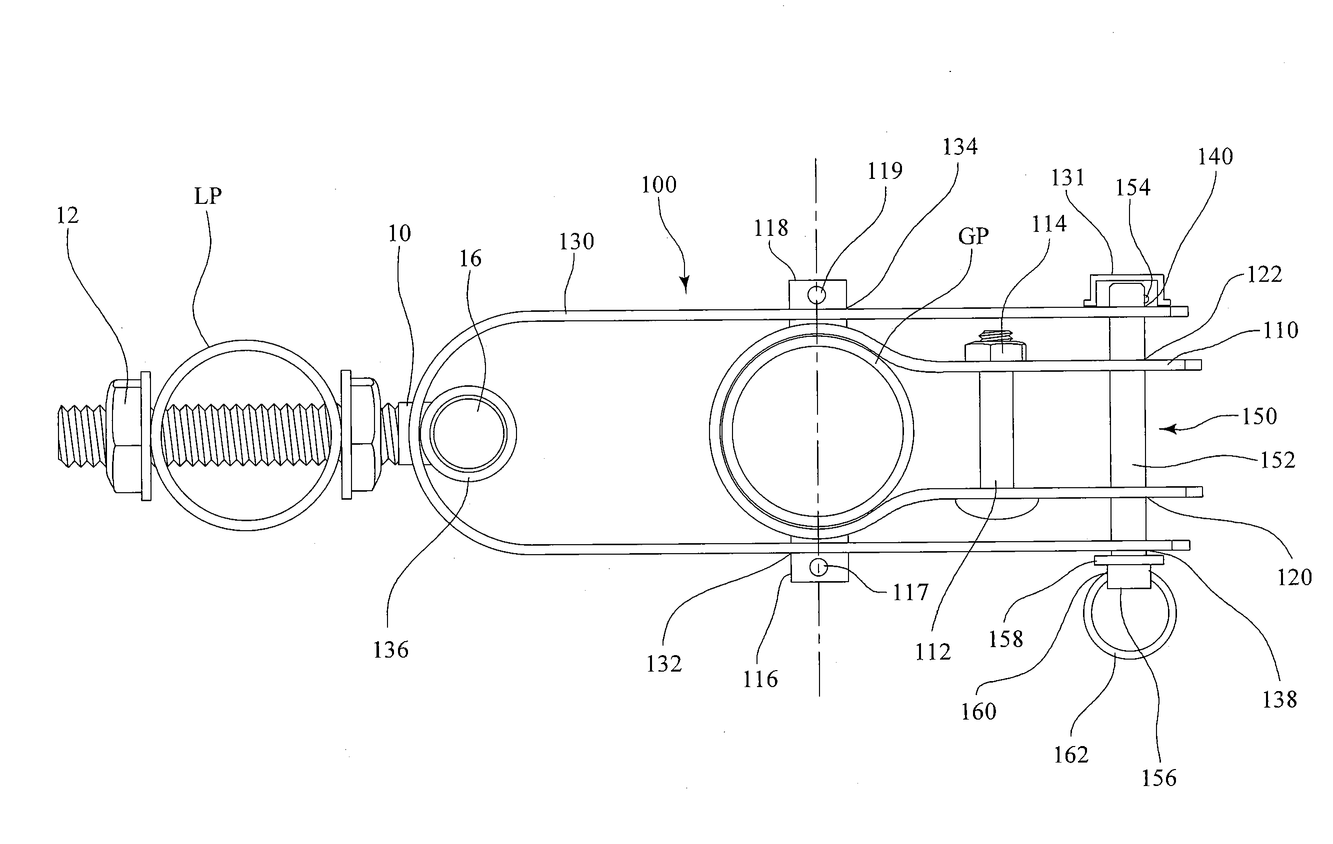
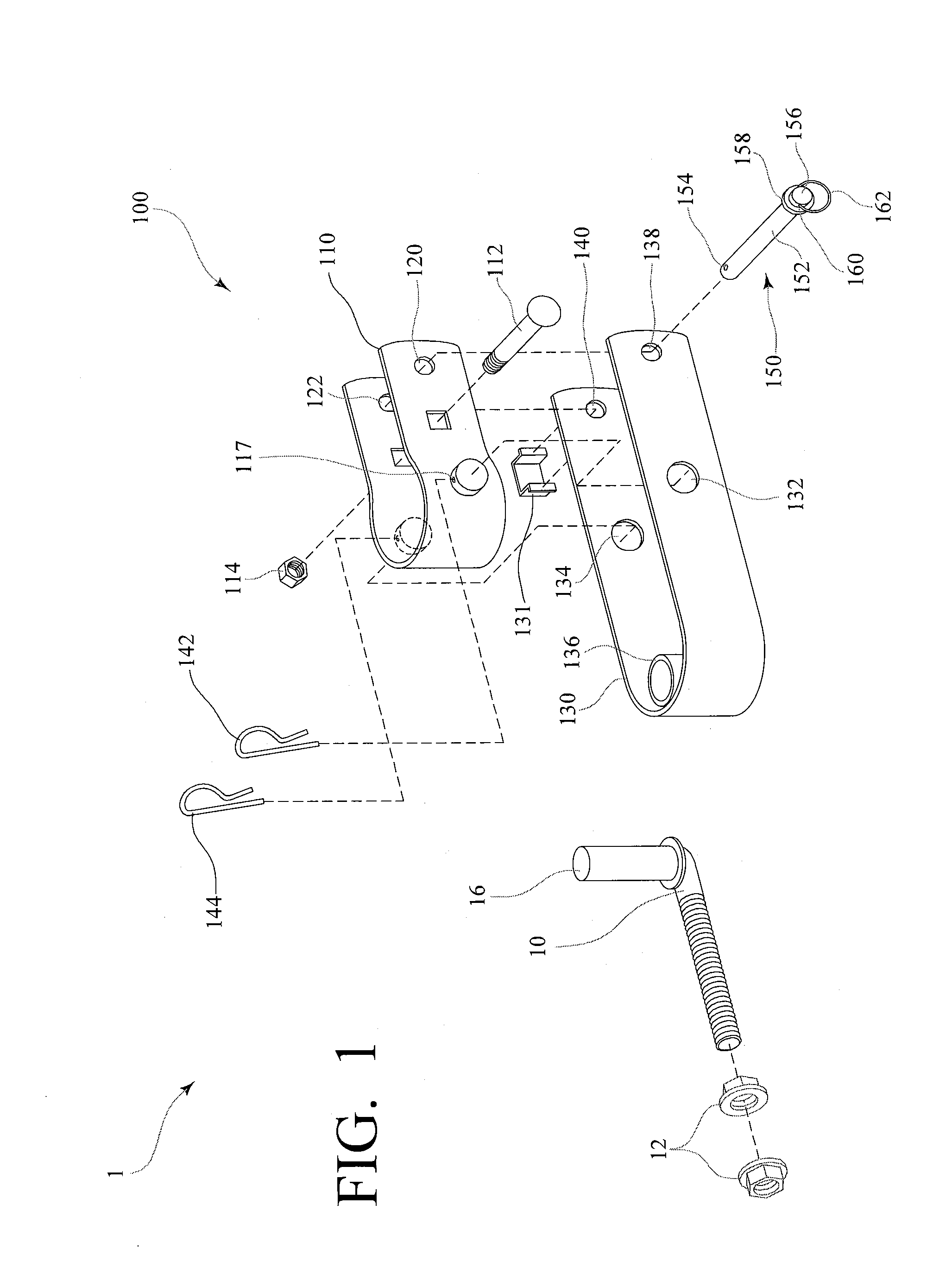
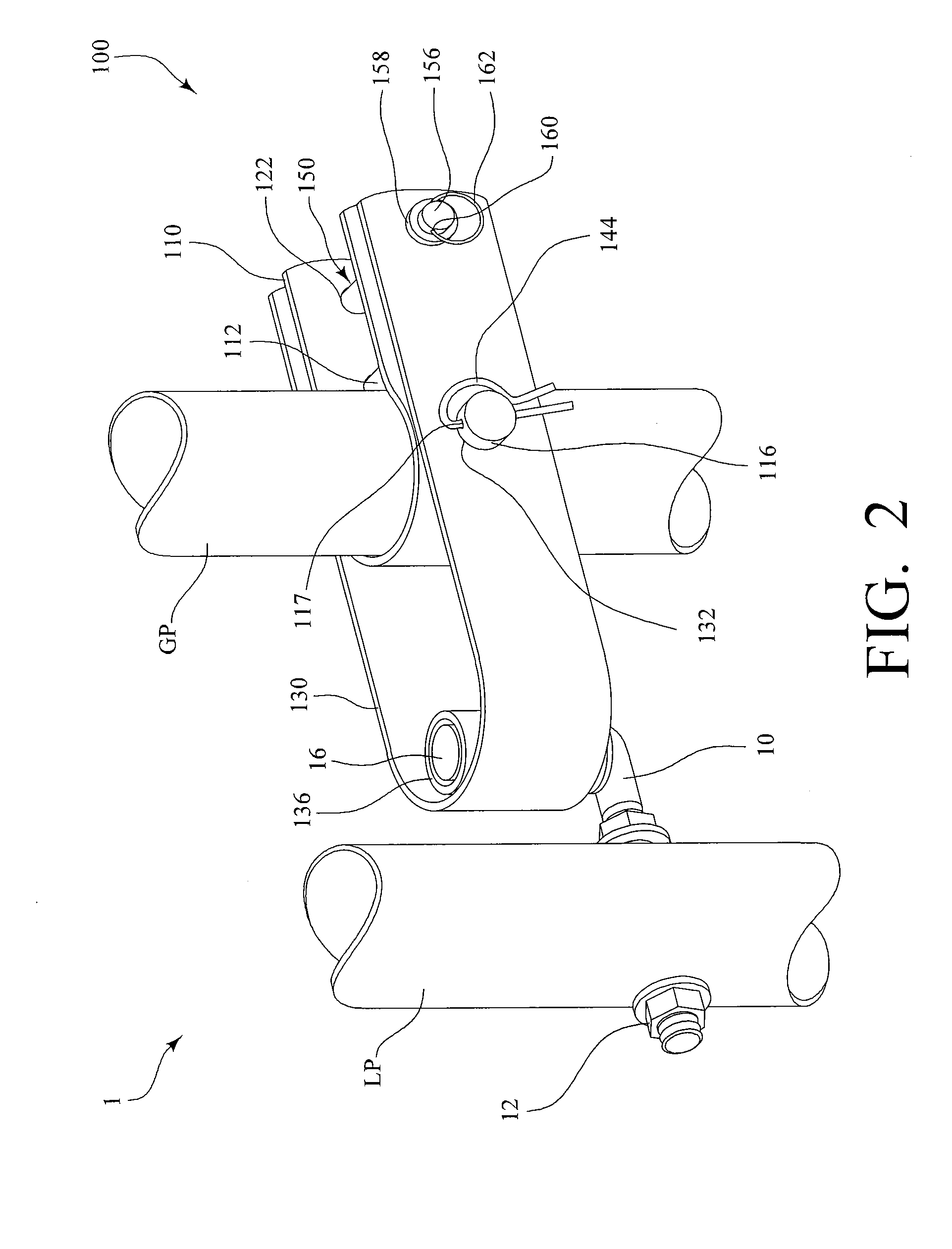
[0021]FIG. 1 shows an embodiment of the present invention —gate stabilizer 1 formed from galvanized steel. In the embodiment shown in FIG. 1, gate stabilizer 1 includes L-shaped support member 10 and stabilizer assembly 100. In the illustrated embodiment, support member 10 is sized to pass through latch post LP as best seen in FIG. 2. Support member 10 is affixed to latch post LP using nuts 12. Support member 10 includes upstanding cylindrical portion 16.

[0022]Still referring to FIG. 1, stabilizer assembly 100 includes fixed member 110. In the embodiment shown in FIG. 1, fixed member 110 is a generally U-shaped member adapted to wrap around the gate post GP as best seen in FIG. 3. In the illustrated embodiment, fixed member 110 is attached to gate post GP by compressing fixed member 110 around gate post GP using bolt 112 and nut 114 (best seen in FIG. 3). Of course other methods of attaching fixed member 110 may be used including, but not limited to, bolting it directly to gate post...


PUM


Abstract

The present invention relates to a gate stabilizer for reducing sag-inducing stress on a gate comprising a support member and a stabilizer assembly, said stabilizer assembly including a rotating member having a first end portion adapted to engage said support member and a fixed member. The present invention further relates to a fence system incorporating said gate stabilizer.

Description

CROSS-REFERENCE TO RELATED APPLICATIONS[0001]Not applicableSTATEMENT REGARDING FEDERALLY SPONSORED RESEARCH OR DEVELOPMENT[0002]Not applicableREFERENCE TO A “MICROFICHE APPENDIX”[0003]Not applicableBACKGROUND OF THE INVENTION[0004]1. Field of the Invention[0005]The present invention generally relates to fence gates. More specifically, the invention is a gate stabilizer intended to eliminate gate sag, reduce the stress on gate hinges, and prevent a gate from being forced open.[0006]2. General Background of the Invention[0007]Gate systems, and particularly livestock gates that are usually heavier and larger than normal fence gates, in which the gate hangs on hinges attached to a gate post but is not otherwise supported are plagued by a unique set of problems. One problem routinely experienced by users of these gates is the tendency of gates to sag in at least two non-exclusive manners. First, the sag may result from the failure of the gate structure itself. Second, the otherwise unsup...

Claims


Application Information

Patent Timeline
Patent Type & Authority Applications(United States)
IPC IPC(8): E05D13/00E05D7/06
CPCE05D5/02E05D5/06E05D7/043E05D2007/0446E05Y2600/61Y10T16/53235E05Y2800/29E05Y2800/682E05Y2900/40E06B11/04Y10T16/31E05Y2600/62
Inventor FABER, ERIC BRETT
Owner FABER ERIC BRETT
Learn More