Image display unit with sensor device mounted to frame

a sensor device and image display technology, applied in the field of image display units with a front frame, can solve the problems of inability to continuously high manufacturing cost of such an image display unit, and inability to maintain continuous and fault-free luminance detection, etc., and achieve the effect of simplifying the recalibration of the sensor devi

Inactive Publication Date: 2008-10-09
EIZO
View PDF7 Cites 47 Cited by
  • Summary
  • Abstract
  • Description
  • Claims
  • Application Information

AI Technical Summary

Benefits of technology

[0006]This and other objects are achieved by providing the sensor device and the front frame with structure to mount the sensor device to the front frame, such that the structure allows the sensor device to be mounted at a plurality of positions on a side of the front frame, so that the luminance can be detected.
[0007]One advantage is that the user is free to choose where to mount the sensor device on the front frame. A user will preferably mount the sensor device where it does not disturb his work on the i

Problems solved by technology

The manufacture of such an image display unit is costly.
Furthermore, the drive means are susc

Method used


Image

  • Image display unit with sensor device mounted to frame
  • Image display unit with sensor device mounted to frame

Examples


Embodiment Construction

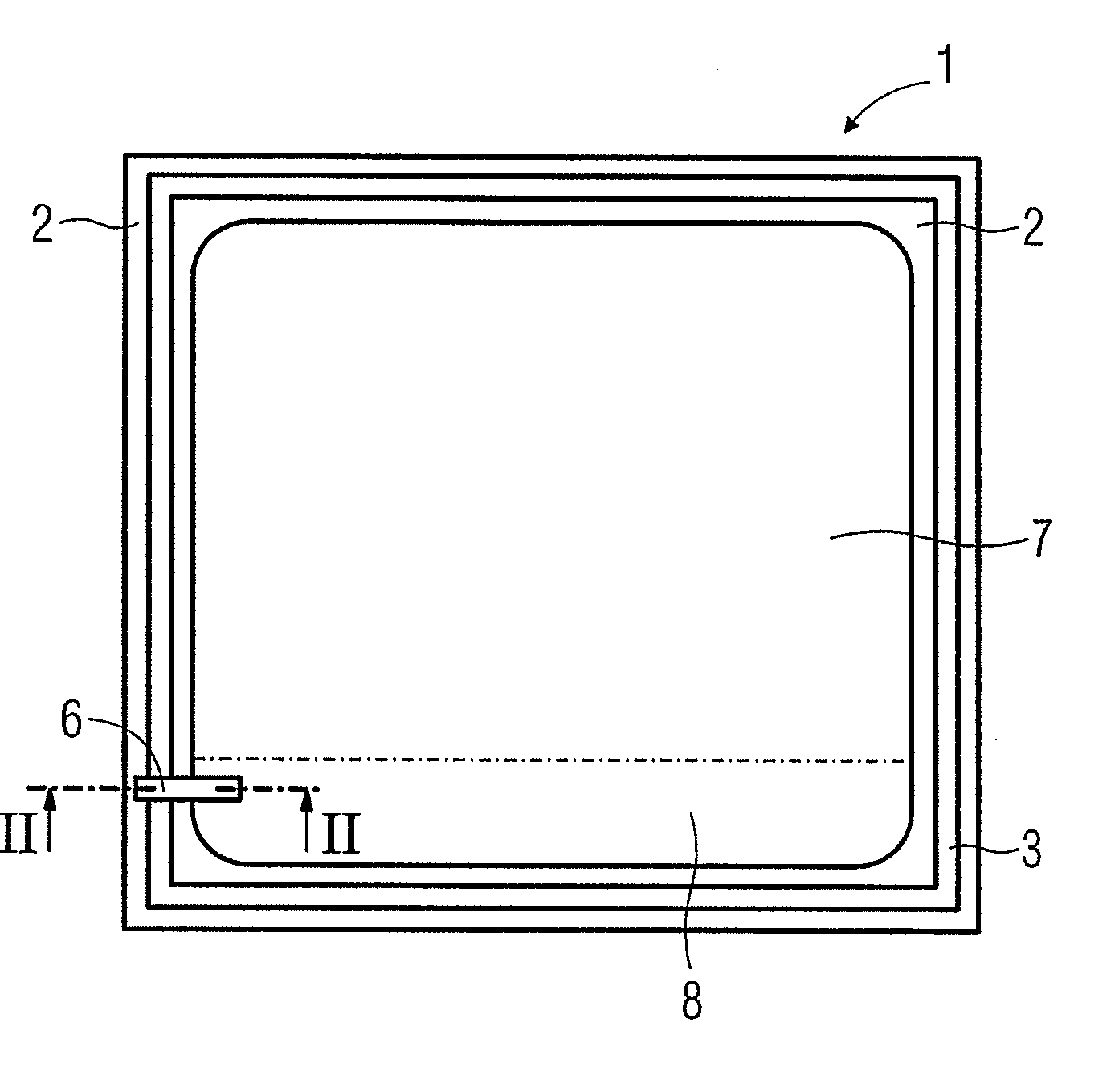
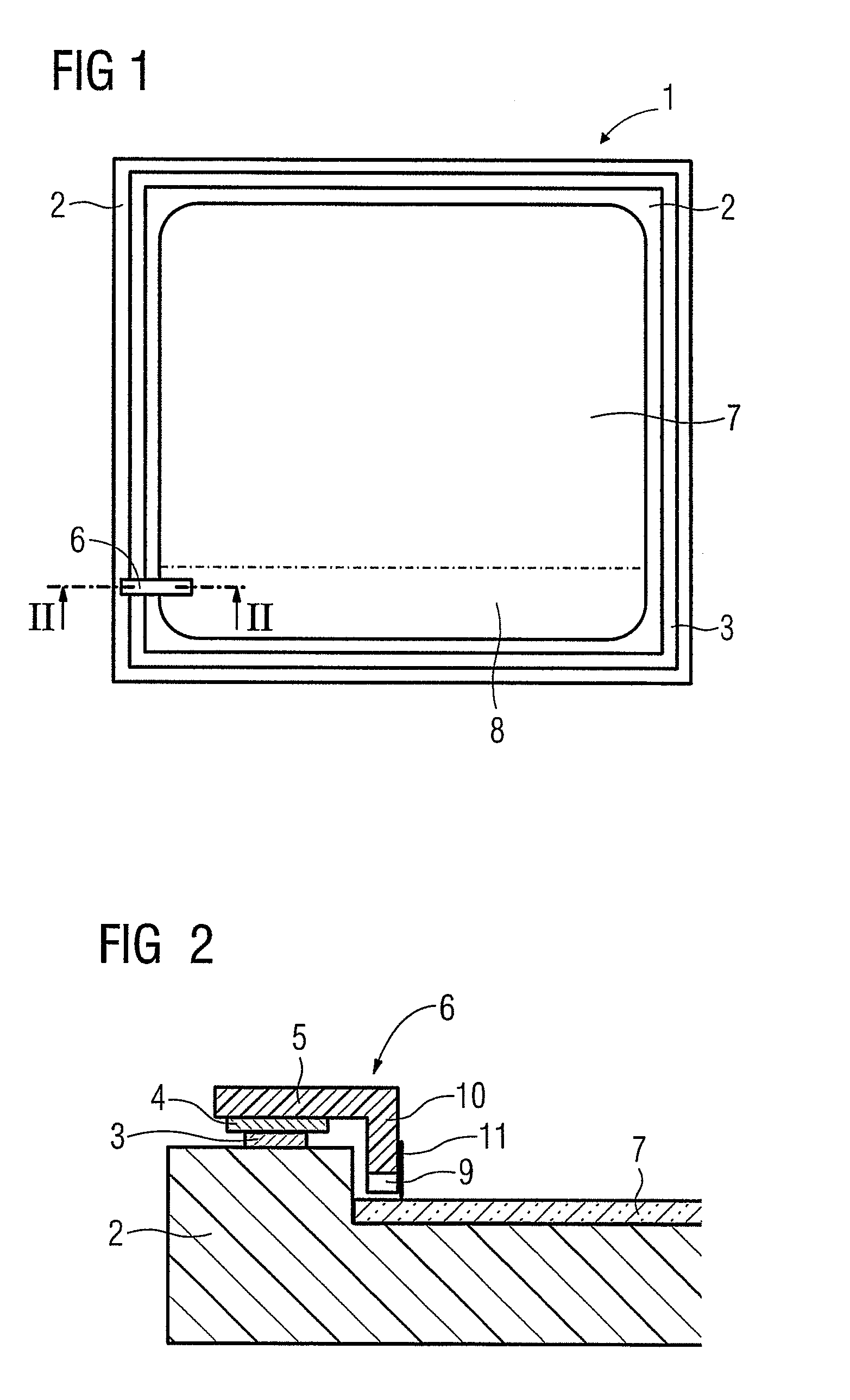
[0014]In FIG. 1, 1 identifies an image display unit with a fixation strip 3 made of a magnetic material arranged on the front frame 2. The magnetic strip 3 is, for example, glued to the front frame 2 or fixed to the front frame 2 in some other manner. The magnetic strip 3 of the front frame 2 is in operative engagement with a magnetic strip 4 of a mounting arm 5 of a sensor device 6, such that the sensor device 6 can be arranged and fixed at any point of the front frame 2. A user will preferably fix the sensor device wherever it does not disturb him during work on the image display unit 1. It may occur, for example, that on a display 7 of the image display unit 1, an application executed by a personal computer connected to the image display unit 1 causes information to be displayed only in the upper area of the display 7, while a lower, narrow area 8 of the display 7 remains unused. In this case, arranging the sensor device 6 on the front frame 2 such that the luminance is detected ...


PUM


Abstract

An image display unit (1) with a front frame (2) and with a sensor device (6) provided with a sensor (9). The sensor (9) is provided for detecting the luminance and/or the color location of an image that displayed on a display (7) of the image display unit (1). To detect luminance, known image display units have a sensor support that, in a non-operating position, is placed in a recess of a frame of a flat screen in an area that cannot be seen by a viewer. Suitable drives make it possible for the sensor support to swivel out from its non-operating position into a position for detecting the luminance. The production of an image display unit of this type is complex. In addition, the drives are susceptible to malfunction, making continuous and fault-free luminance detection impossible. The disclosed arrangement avoids these drawbacks.

Description

[0001]This is a Continuation of International Application PCT / EP2006 / 067092, with an international filing date of October, which was published under PCT Article 21(2) in German, and the complete disclosure of which, including amendments, is incorporated into this application by reference.FIELD AND BACKGROUND OF THE INVENTION [0002]The invention relates to an image display unit with a front frame and with a sensor device provided with a sensor. The sensor is provided to detect the luminance and / or the color location of an image that can be displayed on a display of the image display unit.[0003]Such an image display unit is disclosed in WO 2005 / 036511. To detect the luminance, this device has a sensor support, which in a non-operating position is arranged in a recess of the frame of a flat screen that is not visible to a viewer. Through suitable drive means, the sensor support can be swiveled out of this non-operating position to a luminance detection position.[0004]The manufacture of...

Claims


Application Information

Patent Timeline
IPC IPC(8): H04N5/222
CPCG01J1/02G01J1/0204G01J1/0271G01J3/02G01J3/0202G01J3/0291G01J3/50
Inventor KUPPER, WALTERNAGEL, UWEPAGET, LAURENCE
Owner EIZO
Why Eureka
Try Eureka