Apparatus and method for driving rotary machine

Inactive Publication Date: 2008-10-16
DENSO CORP
View PDF14 Cites 81 Cited by
  • Summary
  • Abstract
  • Description
  • Claims
  • Application Information

AI Technical Summary

Benefits of technology

[0013]It is therefore a first object of the present invention to provide a rotary machine driving apparatus and method, wherein drive control can be restored without stopping the operation of a rotary machine driven by a sensorless method before the rotary machine is completely brought into a state of loss of synchronism. For attaining the first objec

Problems solved by technology

If a trouble occurs in such a driving apparatus or load fluctuation occurs, it can be brought into a state of loss of synchronism in which it cannot drive the motor as intended any more.
However, according to this technique, in case of a motor or the like for driving an electric vehicle, it is inappropriate to stop the rotation of the motor while the vehicle is traveling even though it has been brought into a state of loss of synchronism.
Those technologies are proposed, because a motor is temporarily rotated in a reverse direction or torque produced in a motor is too large, and this causes over-speed and loss of synchronism, resulting in a lengthened starting time in the conventional apparatus.
However, the proposed circuit for varying an excitation frequency is complicated, and this inevitably increases the size of the circuit.
According to this technology, limitation is imposed on a permitted period for which detection of a time when the predetermined electrical angle occurs is permitted.
In these cases, it is difficult to control the rotating state of the motor as desired.
There are cases where, for example, power supply voltage or the load on a motor abruptly fluctuates and this causes the rotational speed of the motor to abruptly fluctuate.
There is a possibility that both a state (loss of synchronism state) in w

Method used


Image

  • Apparatus and method for driving rotary machine
  • Apparatus and method for driving rotary machine
  • Apparatus and method for driving rotary machine

Examples


fifth embodiment

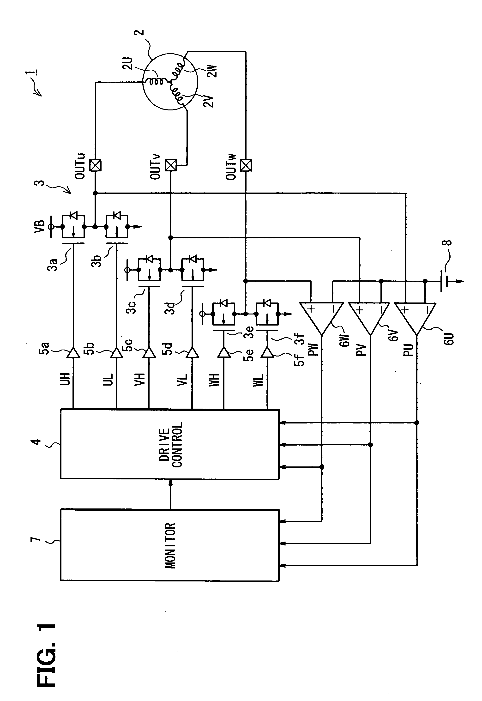
[0132]In a fifth embodiment illustrated in FIG. 11, a rotary machine driving apparatus 1 is configured to drive a motor for driving, for example, a mini disk (MD) or a hard disk drive (HDD). This rotary machine driving apparatus 1 is similar to that of the first embodiment (FIG. 1), but has no loss-of-synchronism monitoring circuit. However, a drive control circuit 4 includes an internal counter (not illustrated) to measure an interval between the edges of the position signals PU′, PV′, PW′ to measure a zero-cross period T60 corresponding to electrical angle of 60° as illustrated in FIG. 12, (g). The zero-cross time point of the induced voltage has a phase delay of an electrical angle of 30° from an appropriate energization time point. Therefore, the drive control circuit 4 generates a commutation pattern by compensating for the phase delay. The time interval corresponding to the electric angle of 30° may be determined as T60 / 2. The waveforms of the output voltage of the inverter un...

sixth embodiment

[0154]In a sixth embodiment illustrated in FIG. 18, a rotary machine driving apparatus is provided for a brushless DC motor 2, which may be provided in a vehicle as a rotary machine.

[0155]The motor 2 is a three-phase motor and an actuator of a fuel pump for an internal combustion engine mounted in a motorcycle. The three phases (U-phase, V-phase, W-phase) of the brushless motor 2 are connected with an inverter 12. The inverter 12 is a three-phase inverter and applies the voltage of a battery 214 to the three phases of the brushless motor 2. To provide conduction between each of the three phases and the positive pole and negative pole of the battery 214, the inverter 12 is so constructed that it includes a parallel connection unit having: switching elements SW1, SW2 (U-phase arm), switching elements SW3, SW4 (V-phase arm), and switching elements SW5, SW6 (W-phase arm). The junction point between the switching element SW1 and the switching element SW2 connected in series is connected ...

seventh embodiment

[0198]In a seventh embodiment, the acceleration of the brushless motor 2 is detected based on a detected value of zero-crossing time, and the setting of a permitted period is corrected based on this acceleration. FIG. 26A illustrates processing for correcting the setting of a permitted period. This processing is repeatedly carried out by the drive control circuit 220, for example, in a predetermined cycle. This series of processing is carried out as follows.

[0199]At S90, the acceleration A of the brushless motor 2 is calculated based on the previous maximum value of the counter and the present maximum value of the counter. The maximum value may be determined based on the value Cm (FIG. 19) of the measuring counter. The maximum value of the counter is for counting the time interval between zero-crossing times, and has correlation with the instantaneous rotational speed between zero-crossing times. For this reason, these two values, the previous maximum value of the counter and the pr...


PUM


Abstract

A motor driving apparatus has a loss-of-synchronism monitoring circuit that monitors the rotation of a rotary machine such as a brushless DC motor to detect a sign of transition to a state of loss of synchronism. When the sign is detected, an energization control circuit temporarily stops driving of the rotary machine to bring it into a free running state, and thereafter carries out control so as to resume driving of the rotary machine. Further, the motor driving apparatus has an inverter and a drive control circuit that controls switching operation of the inverter based on rotation of the rotary machine.

Description

CROSS REFERENCE TO RELATED APPLICATION[0001]This application is based on an incorporates herein by reference Japanese patent applications No. 2006-323947 filed on Nov. 30, 2006, No. 2006-329430 filed on Dec. 6, 2006, No. 2007-25840 filed on Feb. 5, 2007, No. 2007-25841 filed on Feb. 5, 2007, No. 2007-25842 filed on Feb. 5, 2007, No. 2007-40958 filed on Feb. 21, 2007, and 2007-232989 filed on Sep. 7, 2007.FIELD OF THE INVENTION[0002]The present invention relates to an apparatus and a method for driving rotary electric machines such as a brushless DC motor, wherein the rotor position of the rotary machine is estimated to determine the energization time point for driving the rotary machine.BACKGROUND OF THE INVENTION[0003]Some of conventional driving apparatuses adopt a position sensorless method so designed as to estimate the rotor position of a brushless DC motor and thereby obtain the commutation time point of the motor and drive it. If a trouble occurs in such a driving apparatus o...

Claims


Application Information

Patent Timeline
IPC IPC(8): H02P23/14H02P6/06
CPCH02P6/06H02P23/14H02P6/12
Inventor AKAMA, SADAHIROAGATSUMA, SHUJIUEDA, NOBUMASAKURODA, MASAHIRONAGATA, KIYOSHIOOTAKE, MASAYA
Owner DENSO CORP
Why Eureka
Try Eureka