Fail-safe circuit for dynamic smartpower integrated circuits

a technology of integrated circuits and failure-safe circuits, applied in logic circuits, pulse techniques, printing, etc., can solve the problems of complex shape of heating pulses applied to each heater element, rapid failure of the chip from over heating, and the complexity of logic circuits used to selectively address power transistors

Inactive Publication Date: 2003-07-17
XEROX CORP
View PDF0 Cites 3 Cited by
  • Summary
  • Abstract
  • Description
  • Claims
  • Application Information

AI Technical Summary

Problems solved by technology

Typically, the heater element array is sequentially fired because the current draw per element is very large and activating all channels together could lead to rapid failure of the chip from over heating.
Additionally, the firing order of the heating elements is frequently a ripple fire pattern and the shape of the heating pulses applied to each heater element is often complex and may be a function of the temperature of the print head.
Accordingly, the logic circuits used to selectively address the power transistors have become increasingly complicated.
However, the charge is always leaking away from the dynamic circuit element storage nodes.
If for some reason, such as a loss of connection to power, or time-dependent logic failures, the refresh event does not occur before the dynamic circuit elements lose state, then faulty circuit operation will occur.
In integrated circuits, such as thermal ink

Method used


Image

  • Fail-safe circuit for dynamic smartpower integrated circuits
  • Fail-safe circuit for dynamic smartpower integrated circuits
  • Fail-safe circuit for dynamic smartpower integrated circuits

Examples


Embodiment Construction

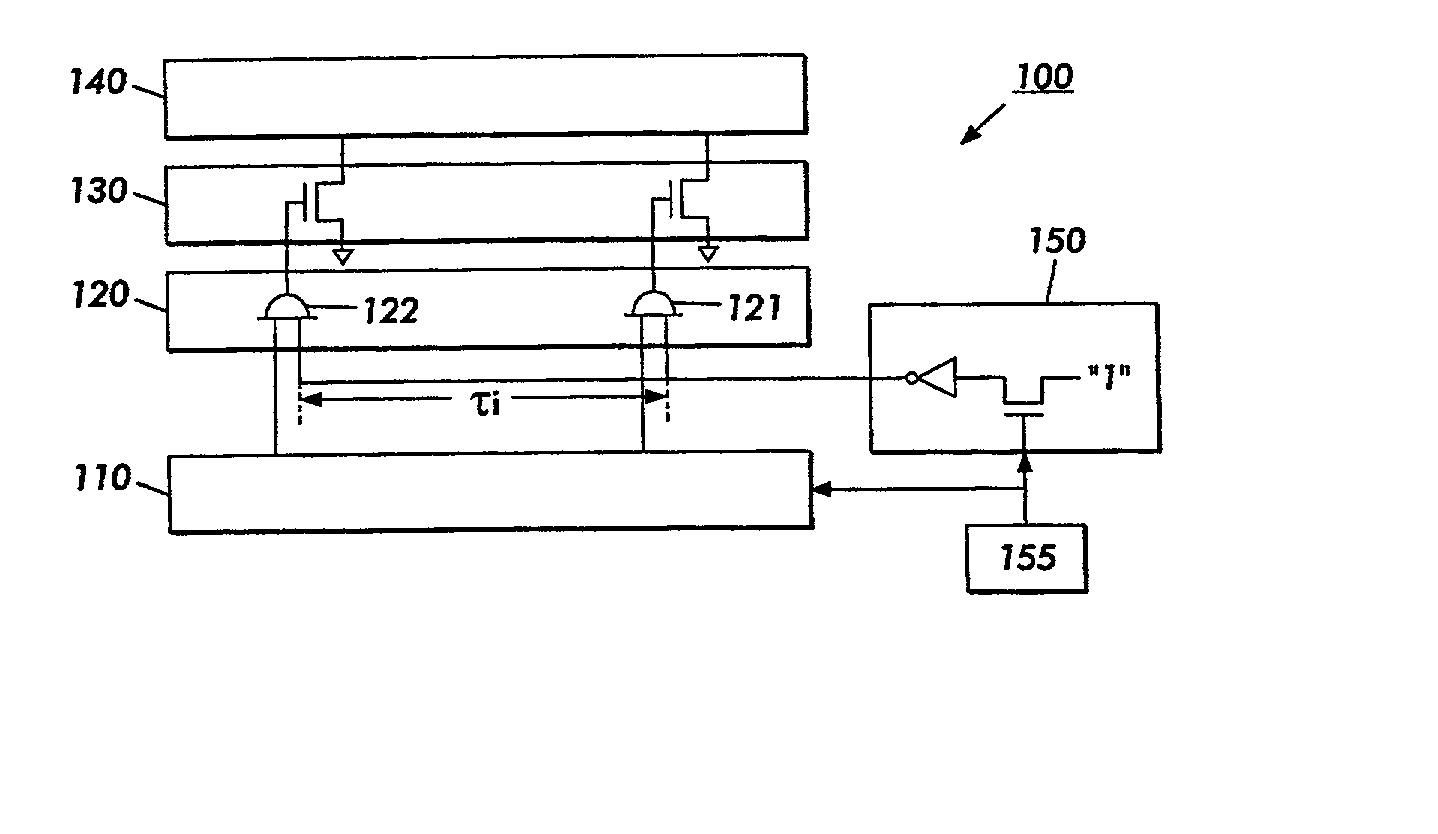
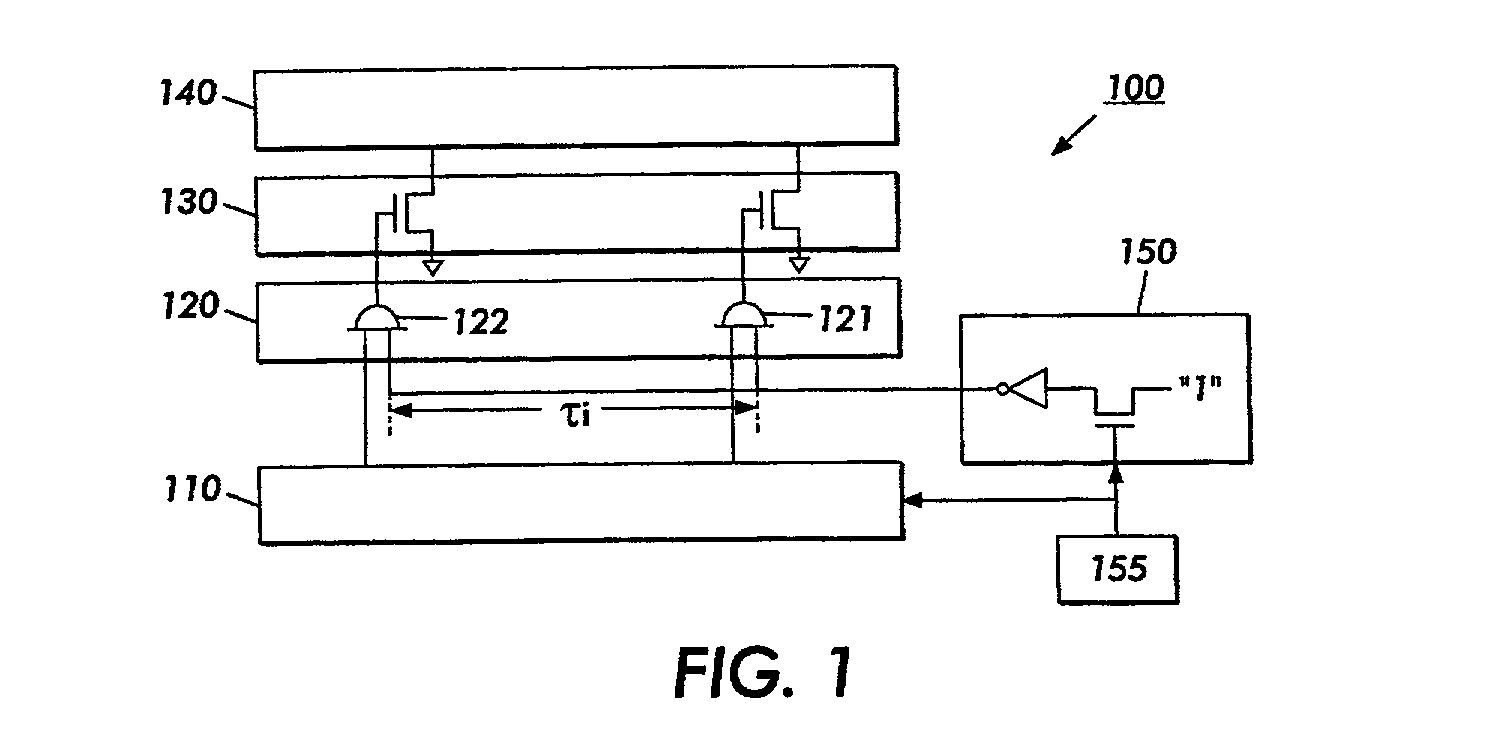
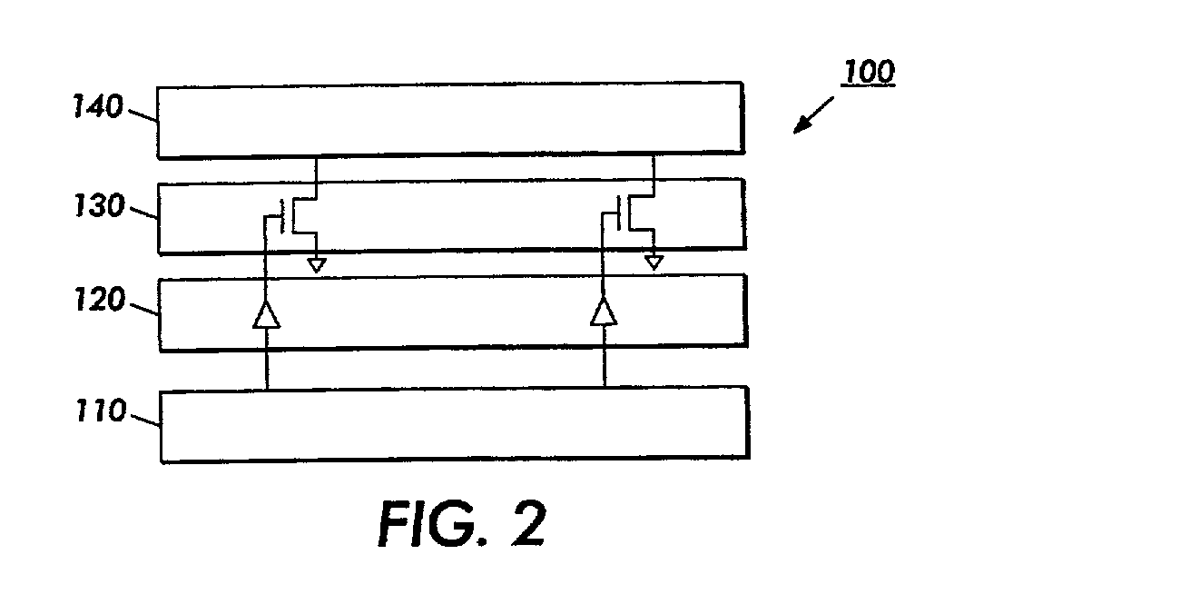
[0027] Various exemplary embodiments of the circuits and methods according to this invention are described using thermal inkjet print head technology. It should be understood that many other micro-fluidic and micro-mechanical systems can also be addressed by dynamic logic circuitry, and may also have catastrophic states that could be encountered with a "loss of state" in the controlling logic section. All of these types of micro-fluidic and micro-mechanical devices are considered to be within the scope of this invention.

[0028] This invention provides a fail-safe circuit which continually monitors the print head circuit refresh event and protects the circuit elements of a circuit that contains one or more dynamic circuit elements when the refresh time .tau..sub.r of one or more of the dynamic circuit elements approaches the hold time .tau..sub.hd of the dynamic circuit elements. In one exemplary embodiment of this invention, a dynamic timer circuit is provided which measures the actu...


PUM


Abstract

A method and Apparatus for protection of semiconductor micromechanical devices that use circuits with dynamic logic addressing is disclosed. In one exemplary embodiment of the invention, a fail-safe circuit is provided for an ink jet print head integrated circuit which prevents a catastrophic consequence of the dynamic logic addressed integrated circuit losing its charge.

Description

[0001] 1. Field of Invention[0002] This present invention relates to a method and apparatus for creating fail-safe electrical components that employ dynamic logic circuitry to switch large power loads or to otherwise control circuits.[0003] 2. Description of Related Art[0004] A thermal ink jet print head selectively ejects droplets of ink from a plurality of drop ejectors. The ejectors are operated in accordance with digital instructions to create a desired image on an image receiving member. The print head may move back and forth relative to the image receiving member to print the image in swaths or the print head may extend across the entire width of an image receiving member, to print the image without any scanning motion.[0005] The ejectors typically comprise capillary channels, or other ink passageways, which are connected to one or more common ink supply manifolds. Ink is retained within each channel until, in response to an appropriate digital signal, the ink in the channel i...

Claims


Application Information

Patent Timeline
IPC IPC(8): B41J2/045B41J2/01B41J2/05H03K19/007
CPCB41J2/0451B41J2/04511B41J2/0458B41J2/04546B41J2/04545
Inventor BECERRA, JUAN J.HAWKINS, WILLIAM G.MORTON, CHRISTOPHER R.CHOI, YUNGRAN
Owner XEROX CORP
Why Eureka
Try Eureka