Rowing Machine Simulators

a simulator and rowing machine technology, applied in the field of rowing machine simulators, can solve the problems of not properly simulating 1 does not properly simulate the forces to which an oarsman is exposed, and increases the likelihood of injury to the oarsman's knee, back and shoulders, etc., and achieves the effect of stable simulator

Inactive Publication Date: 2008-10-23
ROWPERFECT
View PDF100 Cites 23 Cited by
  • Summary
  • Abstract
  • Description
  • Claims
  • Application Information

AI Technical Summary

Benefits of technology

[0025]It can therefore be seen that there is advantageously provided an energy storage device for use with a rowing machine simulator which allows the simulation of some forces experienced by an oarsman when rowing a boat on the water. Furthermore, it will be appreciated by those skilled in the art that use of the dynamically balanced rowing machine simulator with the energy dissipation device (flywheel) configuration provides a more stable simulator.

Problems solved by technology

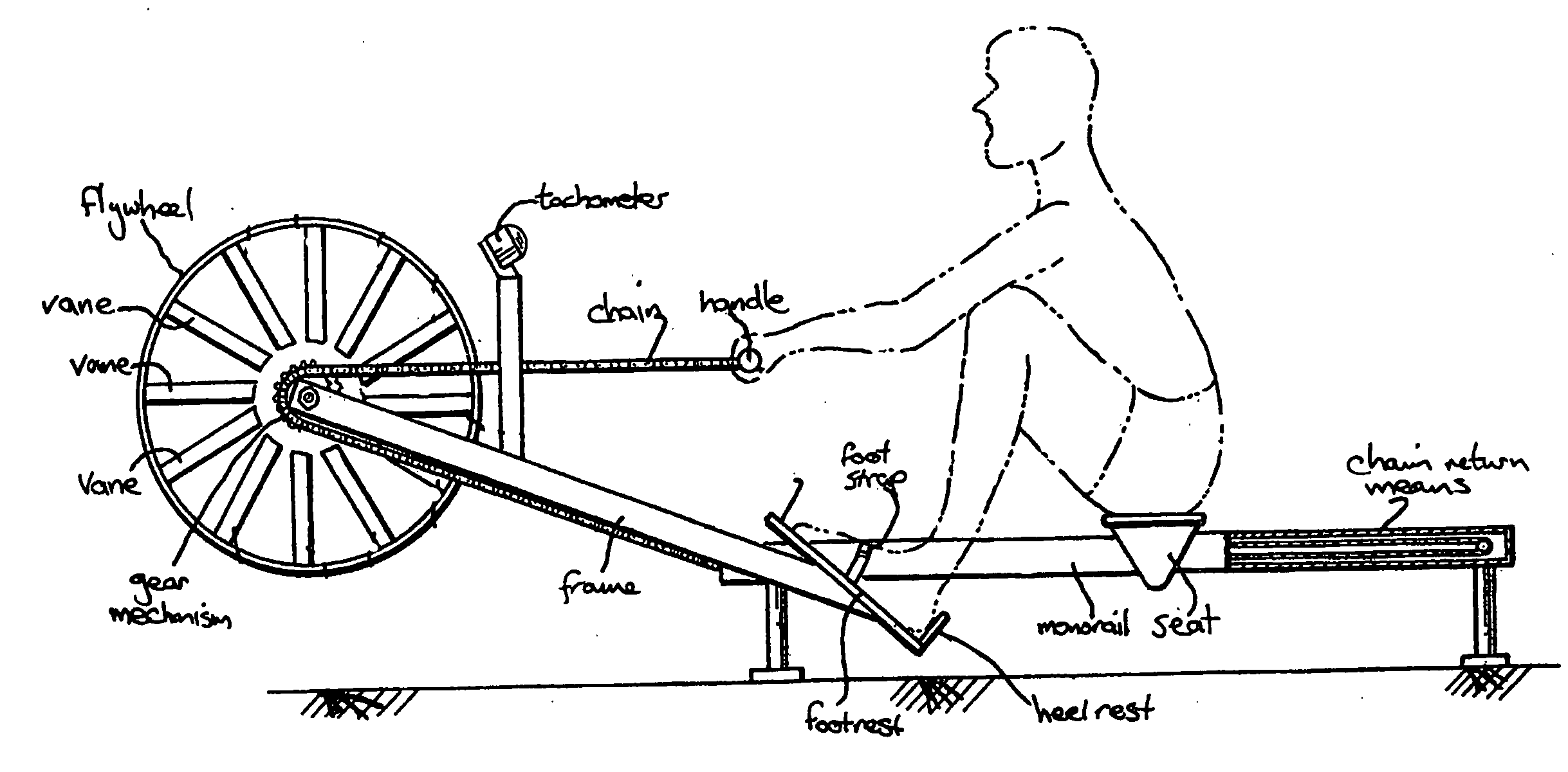
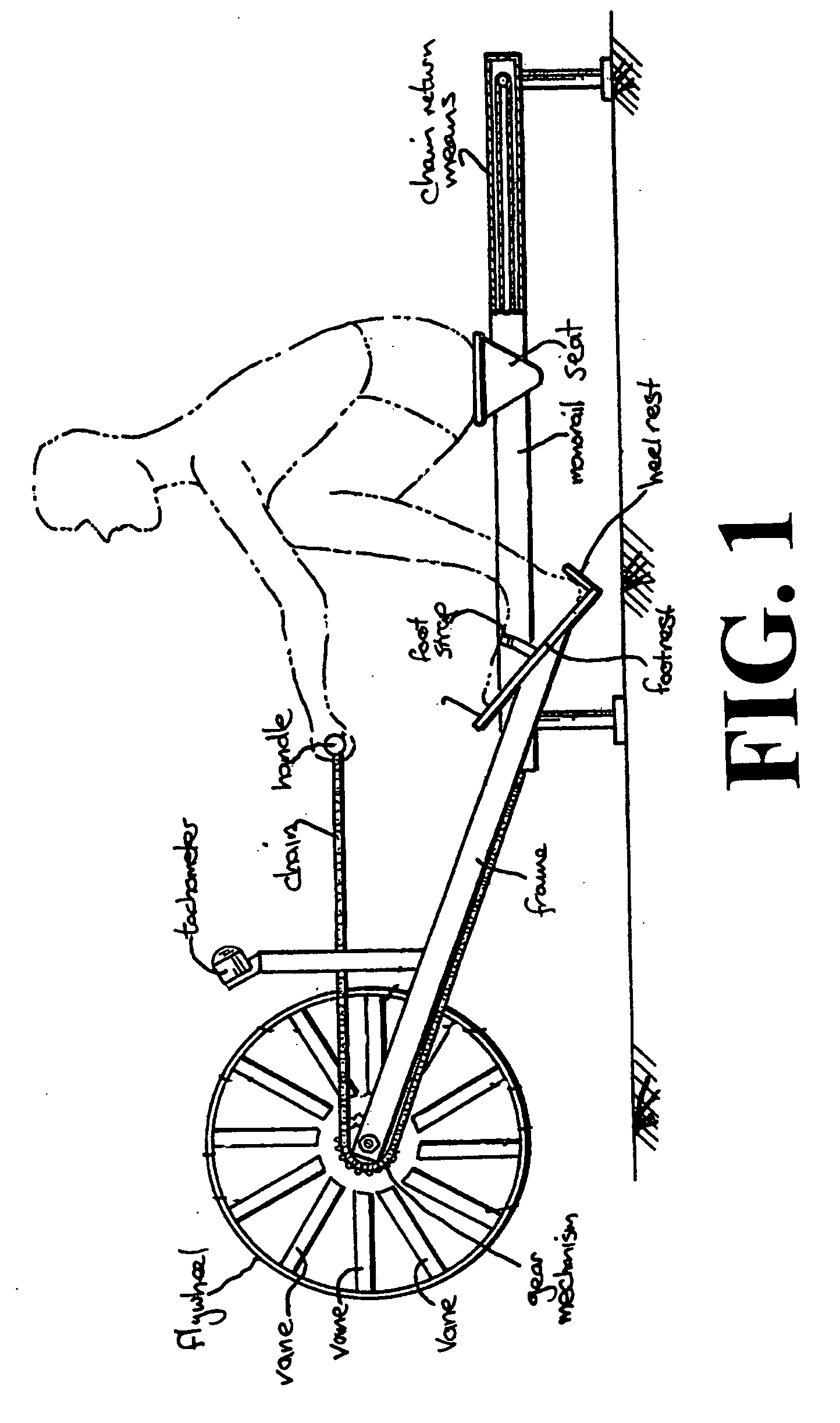
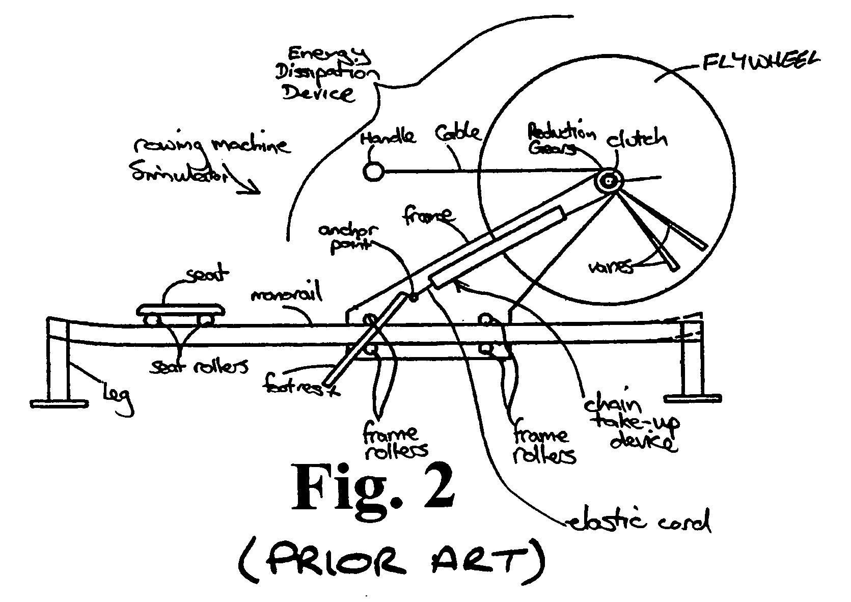
Unfortunately, static rowing machine simulators such as the example shown in FIG. 1 do not properly simulate the forces an oarsman is exposed to during normal rowing action.
As such, the known static rowing machine simulators are acknowledged by health professionals as being potentially detrimental to the oarsman by increasing the likelihood of injury to the oarsman's knee, back and shoulders.

Method used


Image

  • Rowing Machine Simulators
  • Rowing Machine Simulators
  • Rowing Machine Simulators

Examples


Embodiment Construction

[0034]Referring to FIGS. 3 to 7 generally, like reference numerals have been used to denote like components. Referring firstly to FIG. 7, there is shown a rowing machine simulator 1 having a rowing handle 2 which is connected to a dynamically mounted energy dissipation device 3. It will be appreciated that the rowing machine simulator 1 can be a machine in which the energy dissipation device 3 is static and not moveable.

[0035]The rowing machine simulator 1 includes an energy storage device 4. The energy storage device 4 is configured to be disposed intermediate the rowing machine simulator handle 2 and the energy dissipation device 3. The energy storage device 4 is configured to elastically absorb a proportion of the force applied to the rowing handle 2 by an oarsman (not illustrated) during the early phase of a simulated rowing stroke. The elastically stored energy in the device 4 is released during later phases of the simulated rowing stroke when the force applied by the oarsman r...


PUM


Abstract

One aspect is an energy storage device for a rowing machine simulator having a rowing handle connected to an energy dissipation device. The energy storage device is configured to be disposed intermediate the rowing handle and the energy dissipation device and configured to elastically absorb a predetermined proportion of the force applied to the rowing handle by an oarsman during the early phase of a stroke. The elastically absorbed energy is released during later phases of said stroke.

Description

[0001]This Utility Patent Application claims priority to Australian Provisional Patent Application No. 2007900315 filed on Jan. 23, 2007, which is incorporated herein by reference.FIELD OF THE INVENTION[0002]The present invention relates to rowing machine simulators and, in particular, to various improvements to and in rowing machine simulators.[0003]The invention has been developed primarily for use with dynamically balanced rowing machine simulators and will be described hereinafter with reference to this application. However, it will be appreciated that the invention is not limited to this particular field of use and is applicable to many different types of rowing machine simulators as would be understood by a person skilled in the art.BACKGROUND OF THE INVENTION[0004]Static rowing machine simulators have been long known for use in both general strength and fitness training, or for use specifically for oarsmen to practice their rowing. In these known static simulators, a seat is ...

Claims


Application Information

Patent Timeline
Patent Type & Authority Applications(United States)
IPC IPC(8): A63B69/06
CPCA63B22/0076A63B2022/0079A63B2071/0063
Inventor CAMPBELL, MARK
Owner ROWPERFECT
Why Eureka
Try Eureka